
Shielding door device for radiation inspection system

Active Publication Date: 2007-04-05
NUCTECH CO LTD +1
View PDF4 Cites 9 Cited by
  • Summary
  • Abstract
  • Description
  • Claims
  • Application Information

AI Technical Summary

Benefits of technology

[0012] With the above configurations, the shielding door device provides the following technical effects.
[0018] 3. Since position limiting devices for the door body is adopted, it can be ensured that the radiation inspection system will not start detection operation before the shielding door has been closed, so that accidental radiation leakage can be prevented.

Problems solved by technology

However, the shielding device adversely affects convenient entry and exit of an examined object into and out of the sensitive region of detention because it is passive.
The shielding device in the passive form cannot be configured in a completely closed form.
Radiation leakage will thus occur so that the shielding effect is not ideal.
Furthermore, the shielding device can be used only vertically due to limitation of its configuration.

Method used


Image

  • Shielding door device for radiation inspection system
  • Shielding door device for radiation inspection system
  • Shielding door device for radiation inspection system

Examples


first embodiment

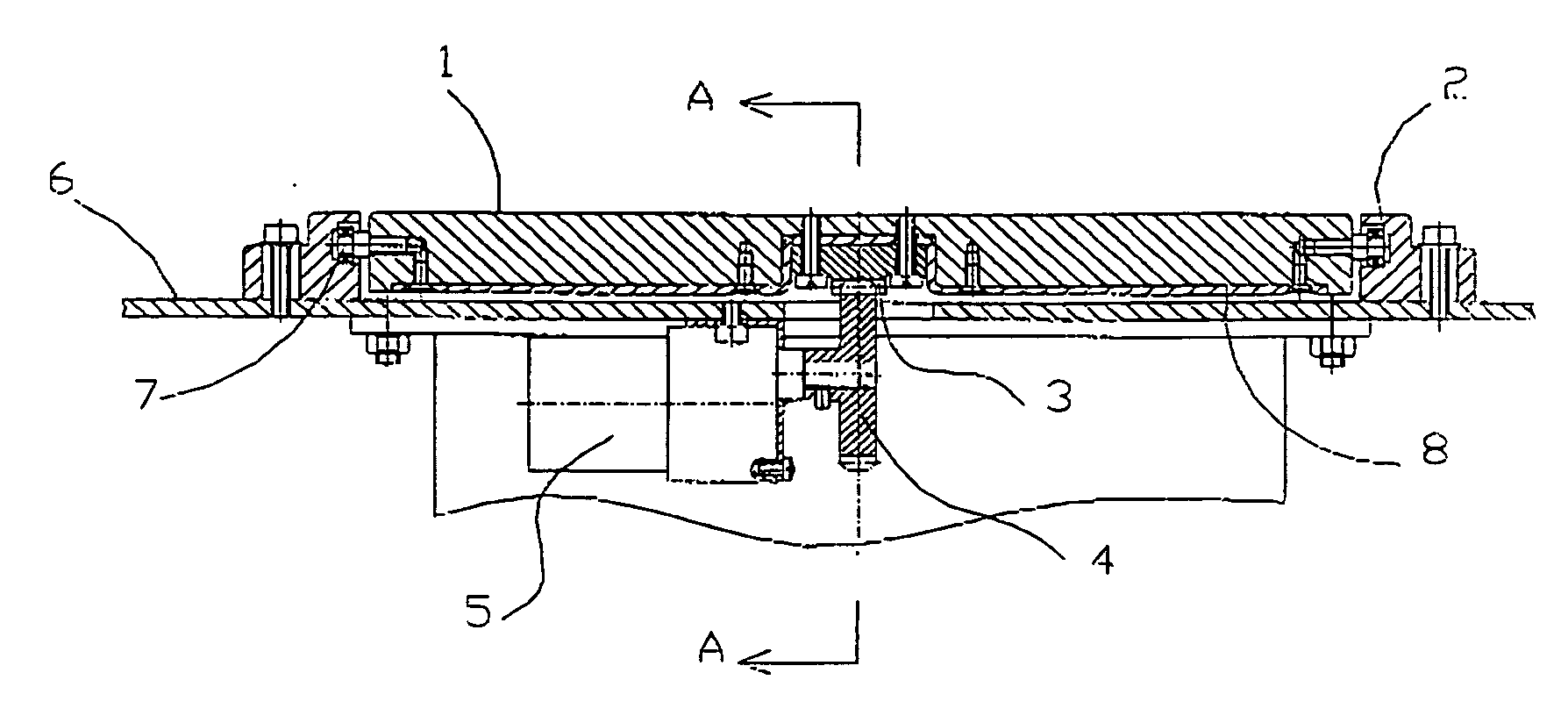
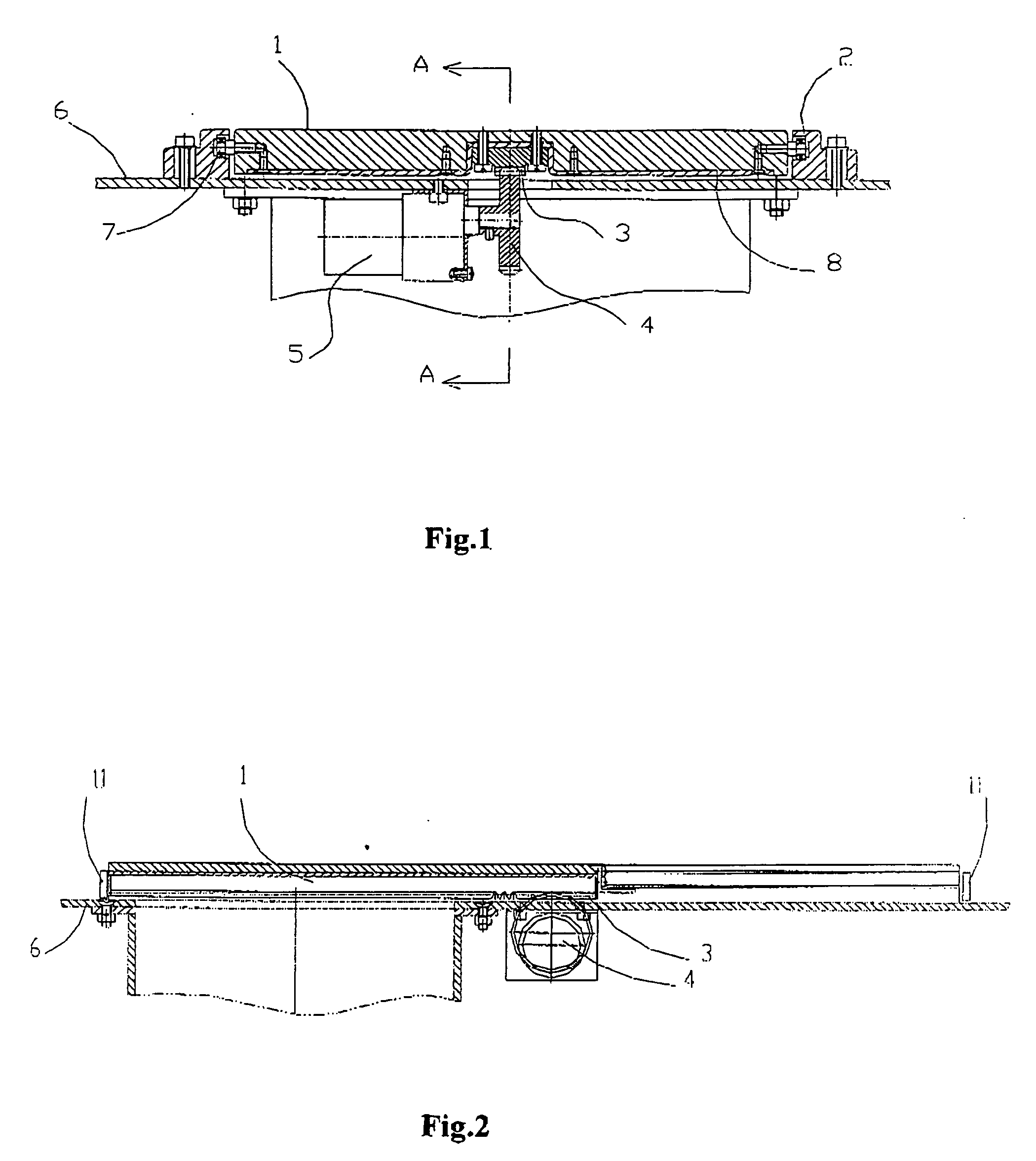
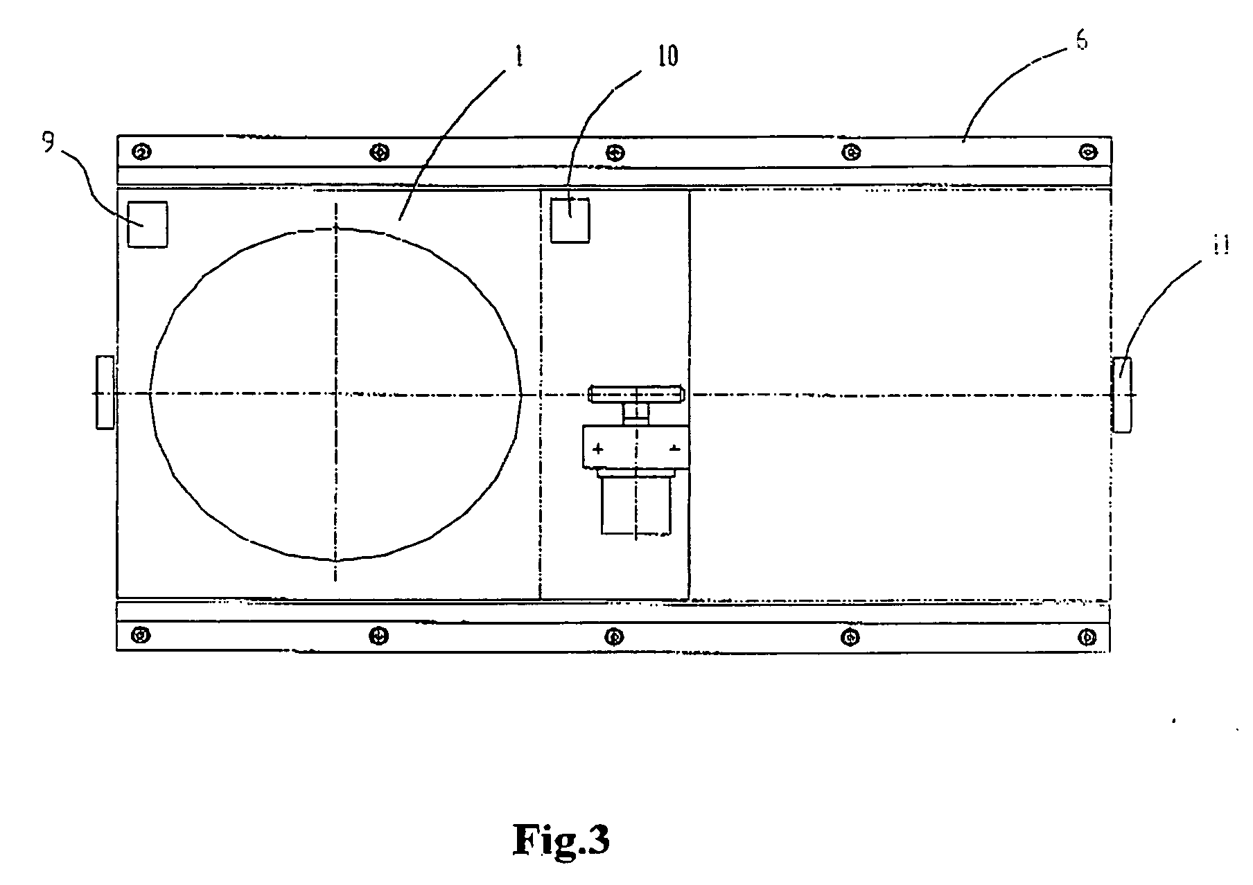
[0024] The embodiments of the present invention will be further described below in conjunction with the accompanying drawings Referring to FIG. 1 to FIG. 3, a shielding door device according to the present application comprises a door body 1, guides 2 (for example, two guides 2) respectively located on two opposite sides of the door body 2, a rack 3, a gear 4 and a motor 5. The door body 1 is made of a metal material having radiation protection function or general metal materials incorporating an additional metal material shielding layer 8 having radiation protection function. The metal material shielding layer 8 may be made of a lead alloy. The two guides 2 are fixed on an upper surface of a frame 6 and the door body 1 is movably connected to the two guides 2 via bearings 7. The rack 3 is fixed on a bottom of the door body 1 and meshed with the gear 4. The gear 4 is coupled with a shaft of the motor 5 fixed on a lower surface of the frame 6. A proximity switch for closing the door ...

second embodiment

[0028] Referring to FIG. 4 to FIG. 5, a shielding door device according to the present application will be explained. The shielding door device comprises a door body 21, a guide 22, and a motor 25. The door body 21 is made of a metal material having a radiation protection function or general metal materials incorporating an additional metal material shielding layer 28 having the radiation protection function. The metal material shielding layer 28 may be made of a lead alloy. The guides 22 are fixed on an upper surface of a frame 6 and the door body 21 is movably connected to the guide 22 via a ball 27. The ball 27 is connected to the door body 21 in such a manner that the ball 27 is capable of rolling. A position limiting sliding groove 23 is disposed in an upper surface of the door body 21 at an edge of the door body 21 diametrically opposite to a shaft of the door body (which will be described latter) . A position limiting sliding member 24 fixed to the guide 22 is movably fitted ...


PUM


Abstract

The present invention relates to a radiation inspection system discloses a shielding door device for a radiation inspection system, comprising a door body, two guides located on two opposite sides of the door body, a rack, a gear and a motor. The two guides are fixed on an upper surface of a frame and the door body is movably connected to the two guides via bearings. The rack is fixed on a bottom of the door body and meshed with the gear. The gear is coupled with a shaft of the motor fixed on a lower surface of the frame. With the above configuration, the present invention is advantageous in automatic and complete shielding of the radiation inspection system without interference. In addition the shielding door can be controlled intelligently, so that accidental radiation leakage can be prevented.

Description

BACKGROUND OF THE INVENTION [0001] 1. Field of the Invention [0002] The present invention relates to a radiation inspection system, particularly to a shielding door device for a radiation inspection system. [0003] 2. Description of the Related Art [0004] Conventionally, a shielding device for an inlet and outlet of a sensitive region of detention of a radiation inspection system is usually a rubber curtain with a lead layer sandwiched therebetween. However, the shielding device adversely affects convenient entry and exit of an examined object into and out of the sensitive region of detention because it is passive. The shielding device in the passive form cannot be configured in a completely closed form. Radiation leakage will thus occur so that the shielding effect is not ideal. Furthermore, the shielding device can be used only vertically due to limitation of its configuration. SUMMARY OF THE INVENTION [0005] The present application is made in view of the above problems of the prio...

Claims


Application Information

Patent Timeline
IPC IPC(8): H05B6/76
CPCE06B3/42E06B5/18G21F7/005G21Y2002/207G21Y2002/501G21Y2004/30G01N23/04G01V5/20
Inventor CHEN, ZHIQIANGLI, YUANJINGLIU, YINONGHU, HAIFENGWU, WANLONGLI, YULANLUO, XILEIZHANG, LIZHAO, ZIRANSANG, BINWANG, HAILIN
Owner NUCTECH CO LTD
Learn More