Fuel-injection valve

a technology of injection valve and fuel valve, which is applied in the direction of valve operating means/release devices, machines/engines, mechanical equipment, etc., can solve the problems of difficult to accurately control fuel injection, and the structure which is able to suppress such bouncing has not yet been achieved, so as to achieve accurate control of fuel injection

Inactive Publication Date: 2007-04-05
TSUCHIYA MASAHIRO +9
View PDF15 Cites 15 Cited by
  • Summary
  • Abstract
  • Description
  • Claims
  • Application Information

AI Technical Summary

Benefits of technology

[0006] The object of the present invention is to provide a fuel-injection valve which is capable of suppressing secondary fuel injection, thereby more accurately controlling the injection of fuel.
[0007] To attain the above object, the present invention provides a secondary oscillation system including a valve element and a force-applying member for applying a force to the valve element, which force is applied to a primary oscillation system. Further, the secondary oscillation system is composed such that the phase angle of oscillation generated by the secondary oscillation system is different from that in the primary oscillation system, so as to suppress any bouncing promoted by the primary oscillation system.

Problems solved by technology

If the bouncing occurs when the valve element is seated on the valve-seat face, a secondary fuel injection occurs after the intended injection, which in turn makes it difficult to accurately control fuel injection.
Also, if the bouncing occurs when the stopping face of the rod butts against the stopper, this also makes it difficult to accurately control fuel injection.
A structure which is able to suppress such bouncing has not yet been achieved.

Method used


Image

  • Fuel-injection valve
  • Fuel-injection valve
  • Fuel-injection valve

Examples


Embodiment Construction

[0030] Hereafter, details of various embodiments will be explained with reference to the drawings.

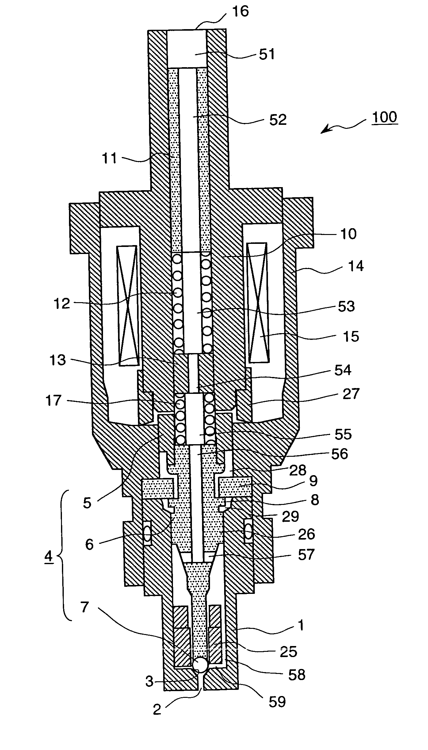
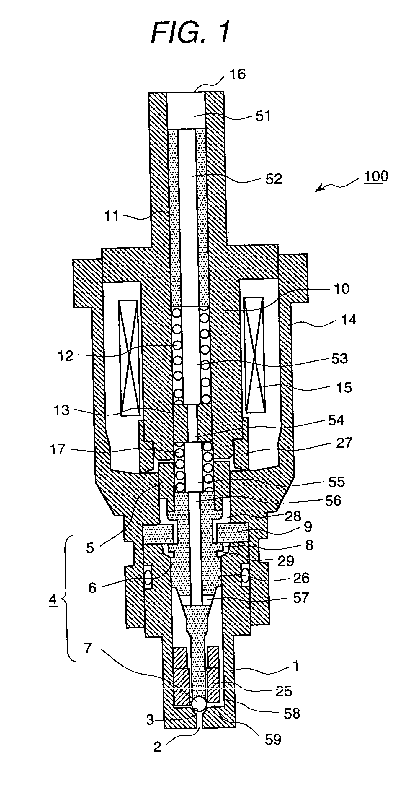
[0031]FIG. 1 shows an electromagnetic fuel-injection valve representing an embodiment according to the present invention. In this embodiment, the side on which there is a fuel-injection hole 2, and the side on which the valve element 4 and the fuel-feeding inlet 16 are located, which is opposite to the fuel-injection hole 2, are defined as the lower and upper sides, respectively, of the electromagnetic fuel-injection valve. Further, the valve axis direction or the direction along the valve axis refers to the direction in which the valve element is driven (the up / down direction).

[0032] In the electromagnetic fuel-injection valve 100 (hereafter referred to simply as the fuel-injection valve), there are an outer cylindrical iron core 14 with a bottom part, which also serves as the casing of the fuel-injection valve 100; an inner cylindrical iron core 10 provided inside the outer iron cor...


PUM


Abstract

A fuel-injection valve includes a fuel-injection hole, a valve element and a valve seat for opening and closing the fuel-injection hole, a force-applying member for applying force to the valve element in a direction of motion of the valve element, and a drive unit for applying force to the valve element in the direction opposite to that of the force applied by the force-applying member; wherein a secondary oscillation system, which interacts with a primary oscillation system including the valve element and the force-applying member, is added to the primary oscillation system, and the phase angle of force applied to the primary oscillation system by the secondary oscillation system is also staggered from that of force applied to the primary oscillation system, which is other than the force applied to the primary oscillation system by the secondary oscillation system, whereby the bouncing of the valve element during opening and closing of the valve is reduced, which in turn makes it possible to achieve very accurate fuel-injection control.

Description

CROSS-REFERENCE TO RELATED APPLICATION [0001] This application is a Divisional application of application Ser. No. 10 / 284,407, filed Oct. 31, 2002, which is a Divisional application of application Ser. No. 09 / 517,046, filed Mar. 2, 2000 (now U.S. Pat. No. 6,474,572). This application relates to and claims priority from Japanese Patent Application No. 11-105253, filed on Apr. 13, 1999. The entirety of the contents and subject matter of all of the above is incorporated herein by reference.BACKGROUND OF THE INVENTION [0002] The present invention relates to a fuel valve injection valve for injecting fuel in an internal combustion engine, and especially to a technique suitable for preventing secondary fuel injection. [0003] Japanese Patent Application Laid-Open Hei 1-1594060 discloses an electromagnetic fuel-injection valve for opening / closing an opening in a valve seat based on an ON / OFF signal having a duty which is determined by a control unit. In this electromagnetic valve, a magneti...

Claims


Application Information

Patent Timeline
Patent Type & Authority Applications(United States)
IPC IPC(8): F02M51/00F02M61/20F16K31/02F02M51/06F02M61/10F02M63/00
CPCF02M51/061F02M51/0682F02M61/205F02M2200/306Y10S239/90
Inventor TSUCHIYA, MASAHIROHIRATA, TOSUKEOKAMOTO, YOSHIOISHIKAWA, TOHRUMAEKAWA, NORIYUKITANABE, YOSHIYUKISEKINE, ATSUSHIKADOMUKAI, YUZOYAMAKADO, MAKOTOABE, MOTOYUKI
Owner TSUCHIYA MASAHIRO
Why Eureka
Try Eureka