Check patentability & draft patents in minutes with Patsnap Eureka AI!

Electrostatic deflection system with low aberrations and vertical beam incidence

a technology of electrostatic deflection and low aberration, applied in the field of electrostatic deflection system, can solve the problems of deteriorating resolution, state-of-the-art electron beam system, and inability to superimpose 120 degree electrostatic deflector electrodes, etc., to achieve vertical incidence and minimize aberration.

Active Publication Date: 2007-04-05
APPLIED MATERIALS INC
View PDF8 Cites 7 Cited by
  • Summary
  • Abstract
  • Description
  • Claims
  • Application Information

AI Technical Summary

Problems solved by technology

In electron beam systems, the deflection process may induce aberrations or otherwise degrade of the focused electron beam causing deterioration of resolution.
Unfortunately, 120 degree electrostatic deflector electrodes cannot be superimposed.
Therefore, the state-of-the-art electron beam systems cannot simultaneously fulfill minimizing aberration and achieving vertical incidence.

Method used


Image

  • Electrostatic deflection system with low aberrations and vertical beam incidence
  • Electrostatic deflection system with low aberrations and vertical beam incidence
  • Electrostatic deflection system with low aberrations and vertical beam incidence

Examples


Embodiment Construction

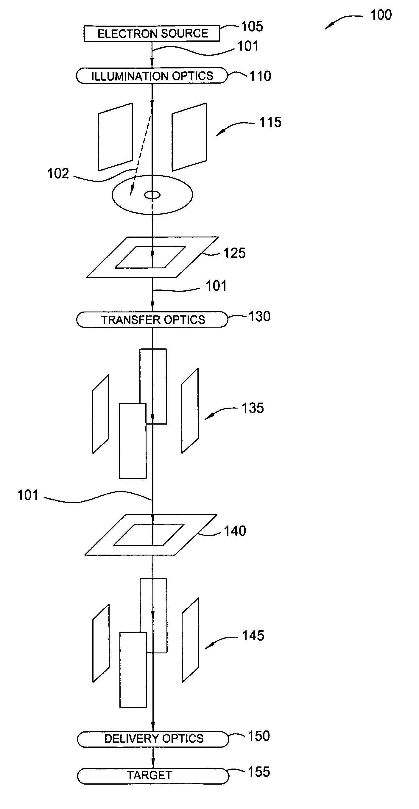
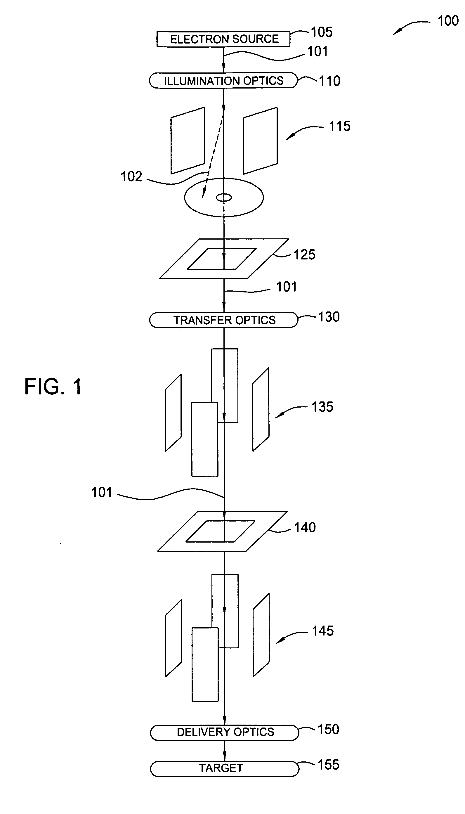
[0024] Embodiments of the present invention may be utilized to improve electron beam deflection. One embodiment provides an electrostatic deflection system with electrodes that minimize aberrations and to achieve vertical incidence simultaneously. By using at least two stages of deflection for a deflection direction, the present invention allows the deflected electron beam to pass a back focal plane of an objective lens while deflection capacitors are not disposed across the back focal plane. As a result, deflection electrodes can have an angle of 120° to minimize aberrations and simultaneously achieve vertical incidence of the electron beam on a target to avoid distortions or changes in magnification with height variations of the target or focus variations.

[0025] While embodiments of the present invention will be described with reference to an electron beam deflection system, those skilled in the art will recognize that the concepts described herein may be applied to control defle...


PUM


Abstract

Embodiments of the present invention may be utilized to improve electron beam deflection. One embodiment provides an electrostatic deflection system with electrodes that minimize aberrations and to achieve vertical incidence simultaneously. By using at least two stages of deflection for a deflection direction, the present invention allows the deflected electron beam to pass a back focal plane of an objective lens while deflection capacitors are not disposed across the back focal plane. As a result, deflection electrodes can have an angle of 120° to minimize aberrations and simultaneously achieve vertical incidence of the electron beam on a target to avoid distortions or changes in magnification with height variations of the target or focus variations.

Description

BACKGROUND OF THE INVENTION [0001] 1. Field of the Invention [0002] Embodiments of the present invention generally relate to an electrostatic deflection system used in electron beam systems. [0003] 2. Description of the Related Art [0004] An electron beam is a group of electrons that have approximately the same kinetic energy and move in approximately the same direction. Electron beam technologies are used in many fields, such as cathode ray tubes (CRT), lithography, scanning electron microscopes, and welding. Electron beam systems, such as scanning electron microscopes, vector and raster beam lithography systems, usually have an electron beam column configured to deflect an electron beam over a target, e.g., a mask or a wafer. [0005] The electron beam column usually have a deflection system to deflect the electron beam over the target either by scanning it, e.g. in image creation, or by arbitrarily deflecting it, e.g. in a vector lithography system. Electron beam systems usually ha...

Claims


Application Information

Patent Timeline
Patent Type & Authority Applications(United States)
IPC IPC(8): H01J37/147
CPCH01J37/1477H01J2237/1518H01J2237/28H01J2237/3175
Inventor WINKLER, DIETERPEARCE-PERCY, HENRYFROSIEN, JUERGENDEVORE, WILLIAM J.
Owner APPLIED MATERIALS INC
Features
  • R&D
  • Intellectual Property
  • Life Sciences
  • Materials
  • Tech Scout
  • Unparalleled Data Quality
  • Higher Quality Content
  • 60% Fewer Hallucinations
Learn More