Ethernet powered device with an internaly controlled auxiliary power ouput

a technology of auxiliary power and ethernet, applied in the direction of data switching details, data switching current supply, emergency power supply arrangement, etc., can solve the problems of door strike being in open circuit failure, tampered, short circuit, etc., and achieve the effect of more simplified wiring

Inactive Publication Date: 2007-04-05
BOGUE EDWARD
View PDF6 Cites 30 Cited by
  • Summary
  • Abstract
  • Description
  • Claims
  • Application Information

AI Technical Summary

Benefits of technology

[0012] This invention allows a power over ethernet powered device to internally control and power an auxiliary power port. This would allow for a system that eliminates the need for an additional power supply for the load and leads to more simplified wiring. Another benefit would be the ability for the PSE to remotely sense the power consumed by the load. For simplicity, this invention will use an access control application as an example. The most common load in access control will be an electric door strike that is connected to this power port. By indirectly allowing the PSE to remotely sense power consumption of the door strike, a computer connected to the PSE could determine if the electric strike is in a state of failure.

Problems solved by technology

If too little power is consumed, the door strike may be in open circuit failure or may have been tampered with.
If too much power is consumed, it could be deduced the door strike may short-circuit or may have been tampered with.

Method used


Image

  • Ethernet powered device with an internaly controlled auxiliary power ouput
  • Ethernet powered device with an internaly controlled auxiliary power ouput
  • Ethernet powered device with an internaly controlled auxiliary power ouput

Examples


embodiment

Preferred Embodiment

[0041] Powered device with auxiliary power output (FIG. 1,2)

Description of Invention

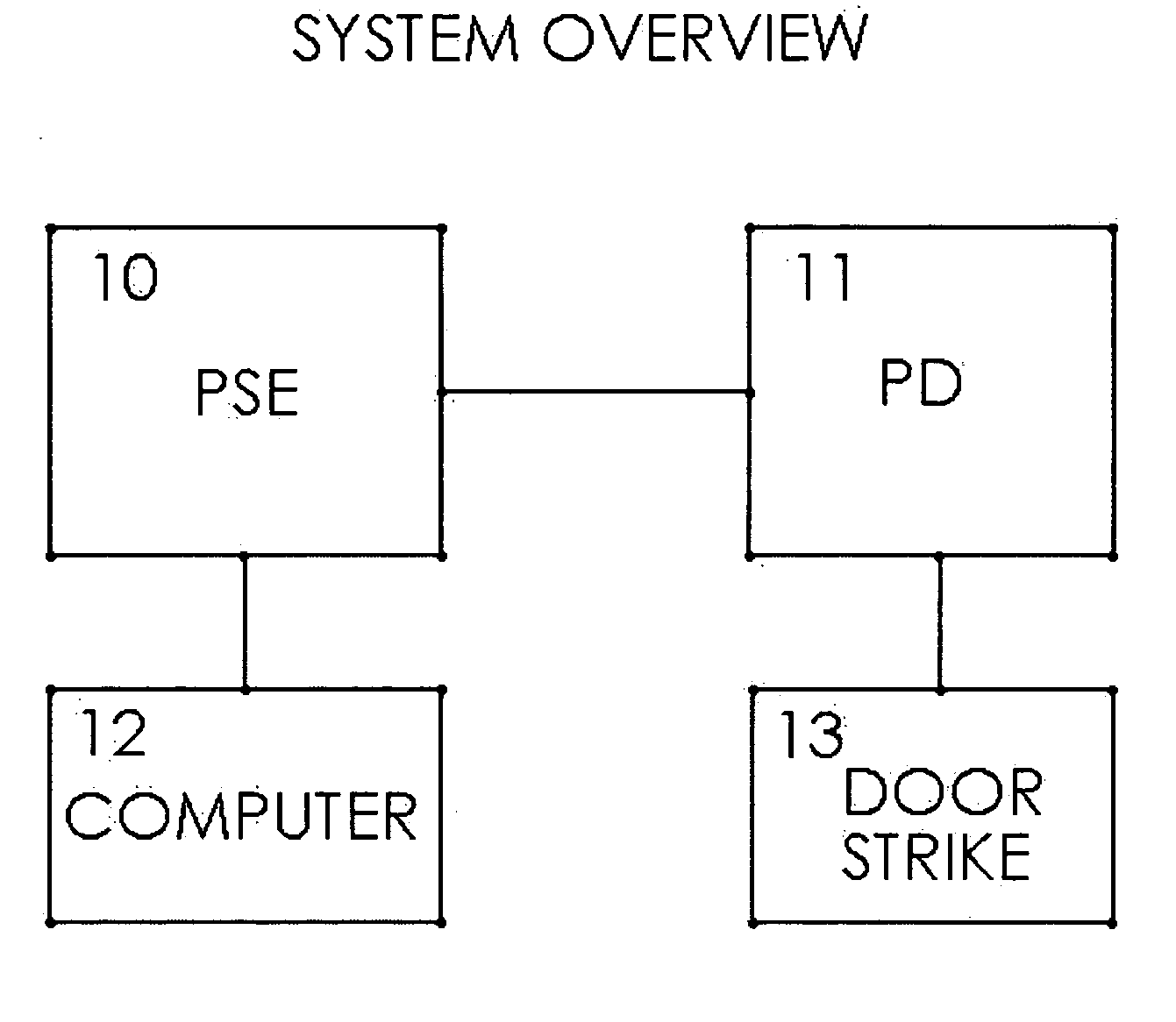
[0042]FIG. 1 shows an example of a system implementing a Powered Device (PD) (11) capable of powering and controlling a door strike (13). The PD (11) will often have a built in identification input device such as a barcode, RF card, or fingerprint reader. The Power Sourcing Equipment (PSE) (10), is typically a server or switch, which is Power Over Ethernet (POE) compliant. The host computer (12), is a typically a standard computer or server which is connected to the PSE (10) via ethernet cable. The Powered device (PD) (11), is connected to a port on the PSE (10) via ethernet cable. The Powered device (PD) (11), is connected to the door strike (13) via wiring of sufficient size to carry the voltage and current specified by the particular door strike (13). The door strike (13) would typically be installed in a fashion to control access of a door or turnstile.

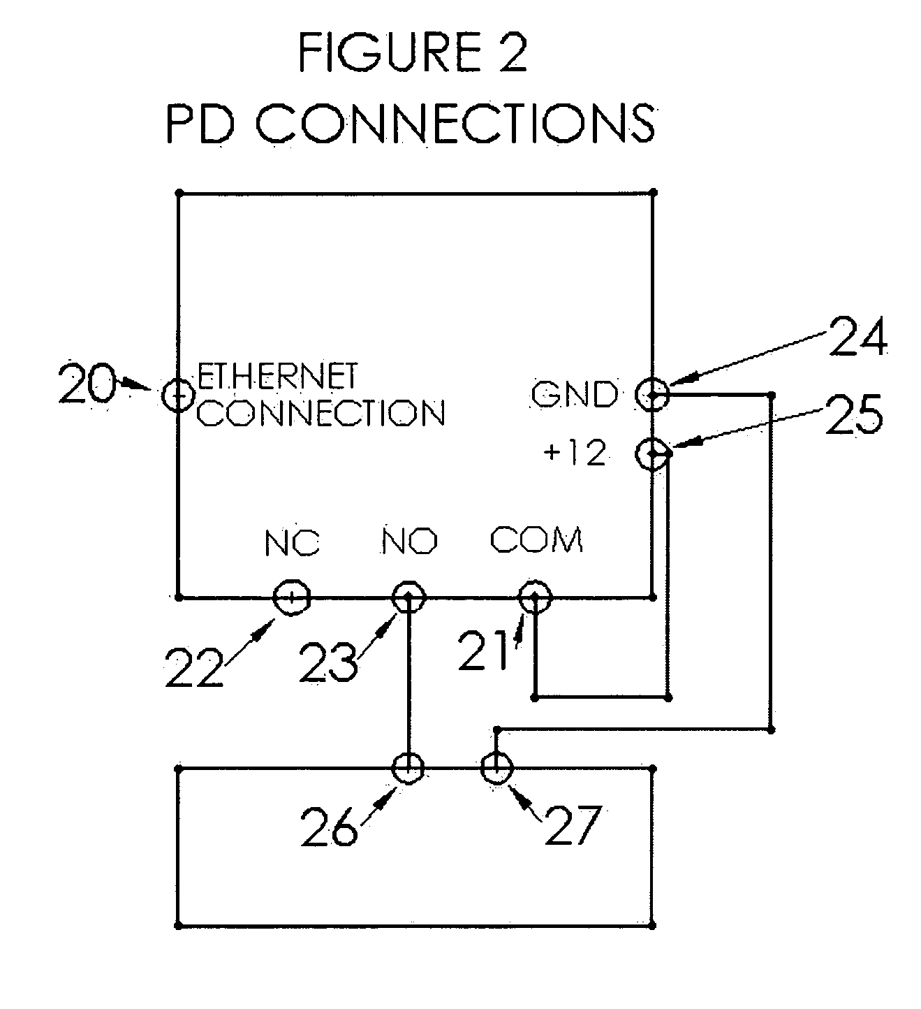
[0043]FIG. 2 shows s...

second alternative embodiment

[0051] PD with Switch Power Output (FIG. 4)

[0052] This embodiment of the invention is similar to the first example, except the requirement to jumper the auxiliary power output to the to the form C relay is eliminated. The auxiliary power output port should not be energized at all time, but rather only when the door strike (13) requires power for access or access restriction. This switching of the auxiliary power output port on and off could be implemented internally through solid-state means or a standard mechanical relay. The advantage of this configuration is simplified wiring in the installation process and increased tamper resistance.

third alternative embodiment

[0053] PD with Built in Diagnostics

[0054] This embodiment of the invention is similar to the first example, except the diagnostics are contained within the PD (11). In this embodiment the tracking of the configuration states within the PD (11) and the theoretical power drawn from the system being in such a state, is done entirely within the PD (11). The PD (11) can then query the PSE (10) through the ethernet network to the power consumed by the PD (11). If the power consumed is outside predetermined parameters, an error indicator could be displayed on the PD (11) if indicators are available, and an error code could be sent to the main host computer.


PUM


Abstract

A powered device (PD) designed to connect to an ethernet cable, which has an auxiliary power port capable of powering a load and switching on and off. In an access control application this auxiliary power port could be connected to an electric door strike. This would eliminate the need for a separate power supply for the door strike and thus, a simplified installation process. This invention would also allow the ethernet powered device (PD) to control and power the load, which would allow the power sourcing equipment (PSE) remote sensing of the power consumed, thus determining if the load is in failure mode. By allowing the powered device (PD) to source power for itself and to provide an auxiliary power output, the power sourcing equipment PSE can be used to detect faults in the load. The power sourcing equipment (PSE) can monitor the current consumed by the PD, and the system can detect if the PD is not drawing sufficient current when the auxiliary power port is activated. If the current is determined to be below a predetermined threshold level, an alert can be issued indicating a broken connection in wires connecting the PD to the load or an open circuit in the load itself.

Description

CROSS-REFERENCE TO RELATED APPLICATIONS [0001] Not Applicable STATEMENT REGARDING FEDERALLY SPONSORED RESEARCH OR DEVELOPMENT [0002] Not Applicable STATEMENT REGARDING FEDERALLY SPONSORED RESEARCH OR DEVELOPMENT [0003] Not Applicable BACKGROUND OF INVENTION [0004] This invention relates to ethernet POE devices, specifically one capable of providing power output to other devices. BACKGROUND [0005] The invention has particular reference to devices powered over networking cable, including ethernet cable, and which are referred to as “powered devices” or “PD” herein. [0006] The invention has particular reference to devices providing power over networking cable, including ethernet cable, and which are referred to as “power sourcing equipment” or “PSE” herein. [0007] The invention has particular reference to networks, including ethernet, and which are referred to as “ethernet” herein. [0008] This invention has particular reference to devices used to electro-mechanically or electro-magneti...

Claims


Application Information

Patent Timeline
Patent Type & Authority Applications(United States)
IPC IPC(8): H02J9/00
CPCE05B47/0046H04L12/10
Inventor BOGUE, EDWARD
Owner BOGUE EDWARD
Why Eureka
Try Eureka