Life cycle extending batteries and battery charging means, method and apparatus
a life cycle extension and battery technology, applied in the field of battery charging, can solve the problems of reducing the capital cost per usable cycle, reducing the capacity of rechargeable batteries, and limited usable life of rechargeable batteries
- Summary
- Abstract
- Description
- Claims
- Application Information
AI Technical Summary
Benefits of technology
Problems solved by technology
Method used
Image
Examples
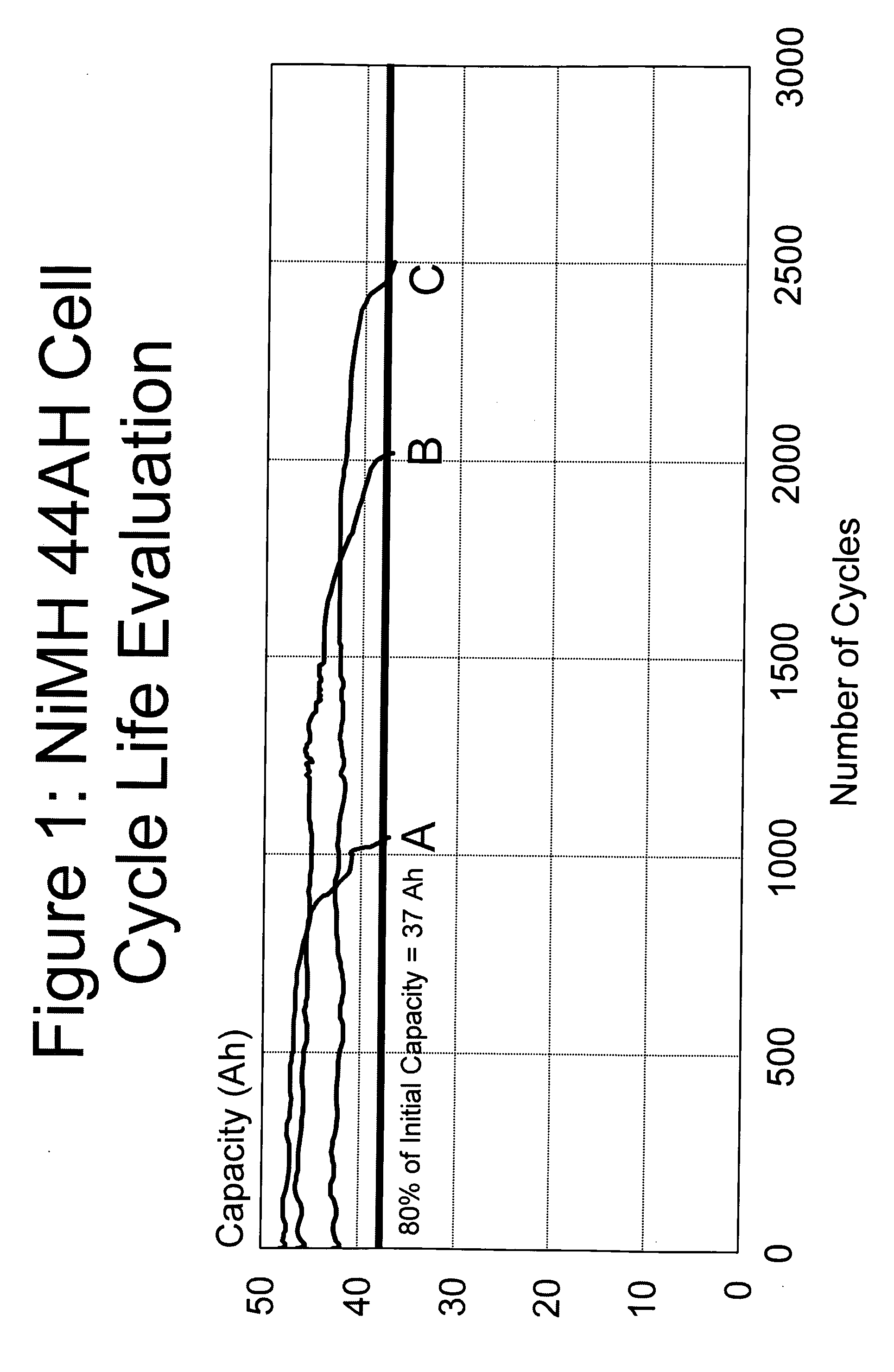
example one (
GRAPH B)
[0090] In this example, the same Nickel Metal Hydride battery of 48 Ah rated capacity with a full charge voltage of 1.525 V is used. Although the full charge voltage of a new battery can be estimated from established principles, the battery is nevertheless characterized to ensure an accurate full charge voltage.
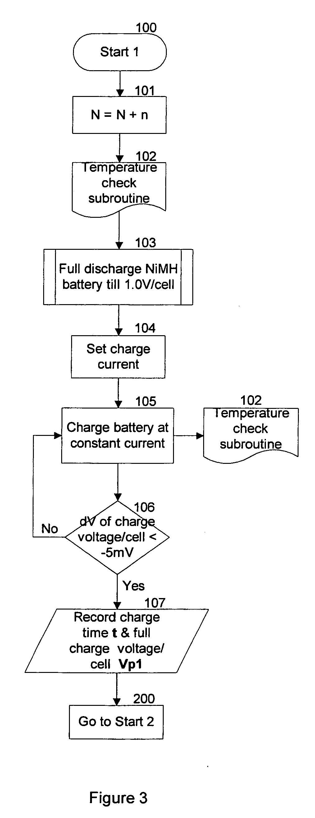
[0091] Firstly, the full charge voltage of the battery in this specific example is ascertained by subjecting the battery to constant current charging at 40 A until the characteristic full charge voltage representing full capacity has been detected, measured or ascertained. The detection of the characteristic full charge voltage can, for example, be by the detection of the occurrence of the −ΔV signal, the change in the charging slope or other appropriate means. Thus, the characteristic full charge voltage is ascertained and confirmed upon the detection of a decrement of 5 mV in the on-charge voltage of the battery.
[0092] After the characteristic full charge voltage ...
example two (
GRAPH C)
[0096] In this example, a NiMH battery of 48 Ah rated capacity with a peak characteristic charging voltage of 1.525 volt is also used.
[0097] Similar to the charging method as described in Example One above, the characteristic full charge voltage of the battery is measured or ascertained by subjecting the battery to constant current charging at 40 Ah until the characteristic full charge voltage representing full battery capacity has been detected.
[0098] After the characteristic full charge voltage (VP1) has been ascertained, subsequent charging cycles of the battery will similarly be terminated upon reaching a pre-determined maximum charging voltage which is below the characteristic full charge voltage VP1. In this specific example, the charging voltage margin is set to be 40 mV below the full charge voltage (VP1). Thus the maximum charging voltage or battery terminal voltage is set to be 1.485 volt, corresponding to 43 Ah or about 90% of the initial rated full battery capa...
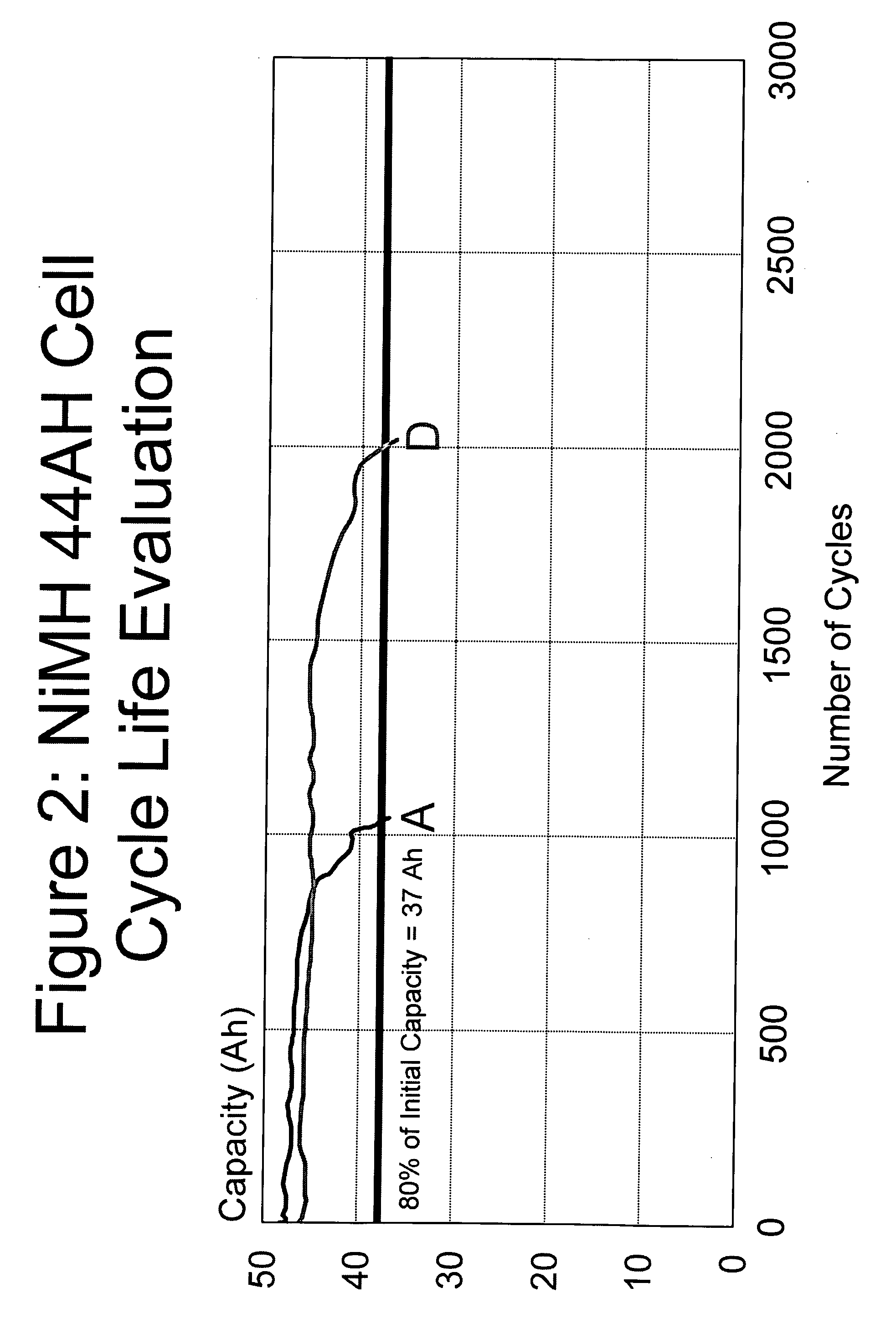
example three (
GRAPH D)
[0099] In this example, a NiMH battery of 48 Ah rated capacity with a peak characteristic charging voltage of 1.525 volt is also used.
[0100] Similar to the charging as described in Example One above, the full charge voltage of the battery is ascertained by subjecting the battery to constant current charging at 40 Ah until the characteristic full charge voltage representing full battery capacity has been detected. Of course, other charging current, depending on the desired rate of charging, can be used without loss of generality.
[0101] After the characteristic full charge voltage (VP1) has been ascertained, subsequent charging cycles of the battery will similarly be terminated upon reaching a pre-determined maximum charging voltage which is below the characteristic full charge voltage VP1. In this specific example, the same constant charging current as used in the characterising cycle is generally used in the subsequent charging cycles and the charging voltage margin is set...
PUM
 Abstract
Description
Claims
Application Information
 - R&D
- Intellectual Property
- Life Sciences
- Materials
- Tech Scout
- Unparalleled Data Quality
- Higher Quality Content
- 60% Fewer Hallucinations
Browse by: Latest US Patents, China's latest patents, Technical Efficacy Thesaurus, Application Domain, Technology Topic, Popular Technical Reports.
© 2025 PatSnap. All rights reserved.Legal|Privacy policy|Modern Slavery Act Transparency Statement|Sitemap|About US| Contact US: help@patsnap.com


