
System and Method for Re-locating an Object in a Sample on a Slide with a Microscope Imaging Device

a technology of imaging device and microscope, which is applied in the field of system and method for relocating an object in a sample on a previouslyexamined slide with an imaging device, can solve the problems of large cost of automatic systems, large impact of interactive systems on routine workflow, and unsupervised manner

Inactive Publication Date: 2007-04-05
TRIPATH IMAGING INC
View PDF21 Cites 37 Cited by
  • Summary
  • Abstract
  • Description
  • Claims
  • Application Information

AI Technical Summary

Problems solved by technology

If properly configured, interactive systems are relatively fast and cost efficient, but the impact of such interactive systems on routine workflow is relatively small.
Automatic rare event detection devices are typically set up in a way that the whole analysis of the slides is done by the system in a totally unsupervised manner, from the loading of the slides onto the scanning stage to the final reporting of the results.
However, such automatic systems are normally quite expensive, so that a relatively high annual volume of slides must be processed to cost-justify the acquisition of such a device.
However, once a manual search procedure is invoked by the operator, any coordinate calibration is usually lost and any objects later selected for review will require the same time-consuming manual relocation procedure to be performed by the operator.
Further, expensive high-precision (typically in the micron range) motorized stages are often necessary for capturing and / or re-locating objects on the slide so as to maintain sufficient reproducibility with respect to the previously-scanned image over the entire extent of the slide.
Also, locating one object generally does little if anything to improve the re-location precision for subsequently-selected objects of interest on that slide.

Method used


Image

  • System and Method for Re-locating an Object in a Sample on a Slide with a Microscope Imaging Device
  • System and Method for Re-locating an Object in a Sample on a Slide with a Microscope Imaging Device
  • System and Method for Re-locating an Object in a Sample on a Slide with a Microscope Imaging Device

Examples


Embodiment Construction

[0023] The present inventions now will be described more fully hereinafter with reference to the accompanying drawings, in which some, but not all embodiments of the inventions are shown. Indeed, these inventions may be embodied in many different forms and should not be construed as limited to the embodiments set forth herein; rather, these embodiments are provided so that this disclosure will satisfy applicable legal requirements. Like numbers refer to like elements throughout.

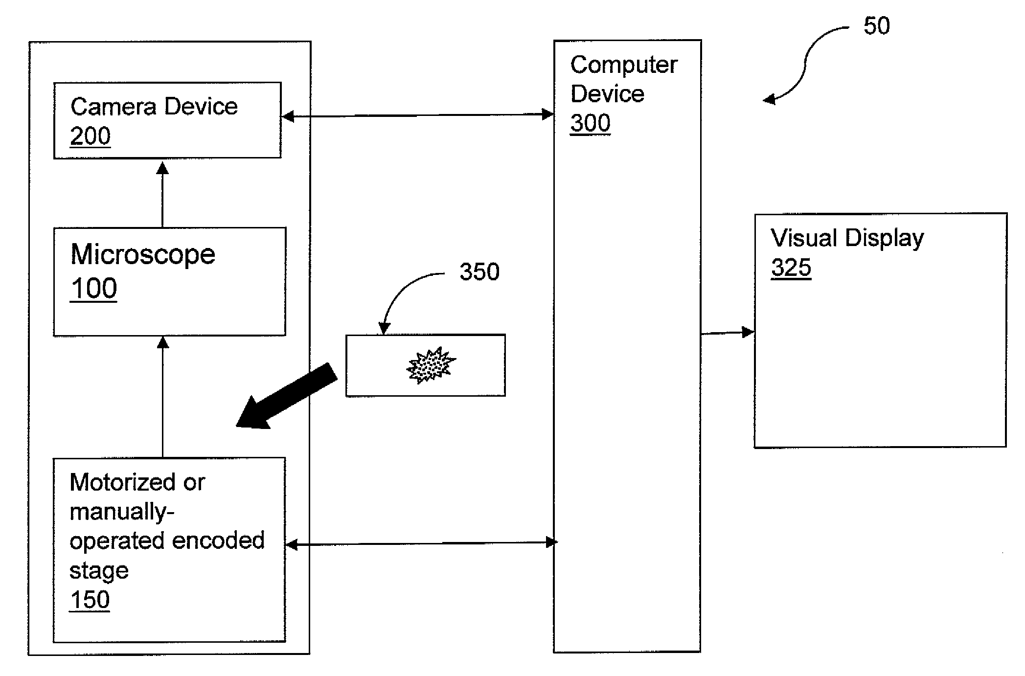
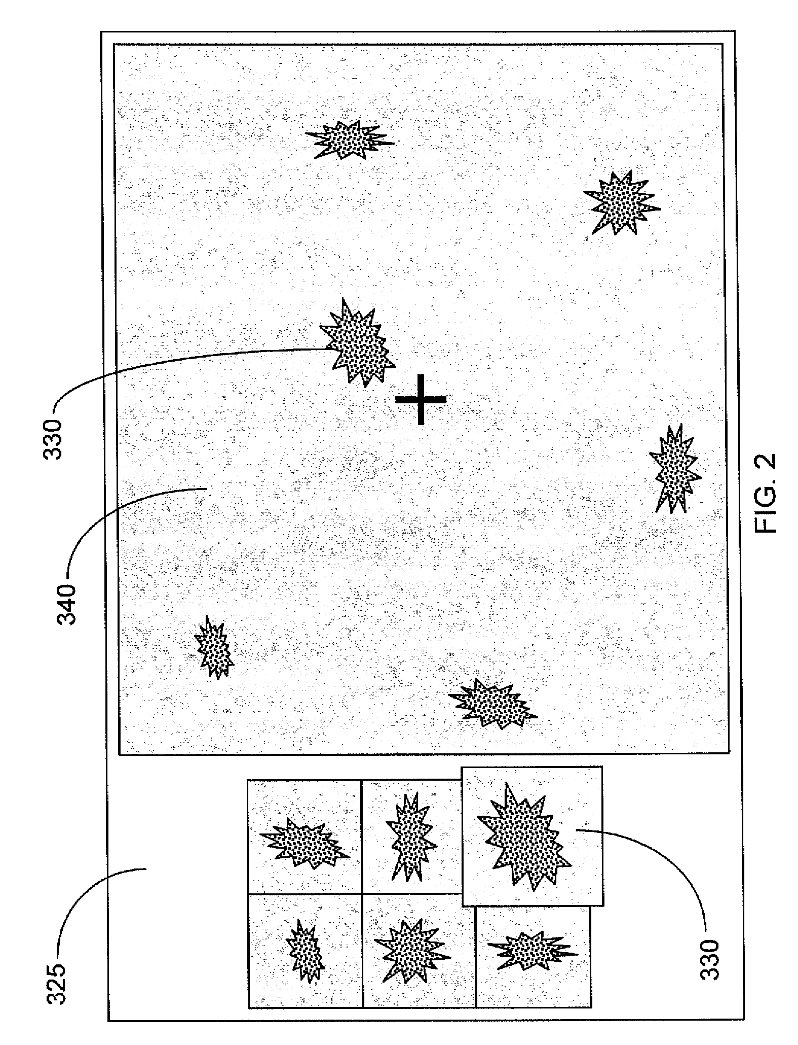
[0024] Embodiments of the present invention are directed to methods for re-locating an object in a sample on a previously-examined slide with a microscopy imaging device. In order to carry out such methods, one embodiment of the present invention implements a system 50 as shown, for example, in FIG. 1, that includes a microscope 100 with built-in automation functionalities (e.g., a Zeiss AxioImager), a motorized stage 150 for the microscope 100 that can be controlled by a computer device 300 or manually oper...


PUM


Abstract

A method of re-locating an object in a sample is provided for a previously-scanned slide having determined objects each with corresponding stored coordinates and a stored image, the objects being mapped relative to each other. The slide is positioned on a microscope stage, stored images of the objects are visually displayed, and a target object is selected. The slide is moved to an estimated coordinate position, corresponding to the coordinates of the target object, and a field-of-view image of the sample is captured for comparison to the stored image of the target. If the target is in the image, an offset between actual coordinates of the located target and the stored coordinates of the corresponding object is determined. The slide is then moved, via the stage, from the estimated coordinate position, according to the offset, to center the target in the image. Associated systems and methods are also provided.

Description

CROSS-REFERENCE TO RELATED APPLICATIONS [0001] This application claims the benefit of U.S. Provisional Application No. 60 / 689,825, filed Jun. 13, 2005, which is incorporated by reference herein in its entirety.BACKGROUND OF THE INVENTION [0002] 1. Field of the Invention [0003] The present invention relates to a system and method for re-locating an object in a sample on a previously-examined slide with a microscope imaging device. [0004] 2. Description of Related Art [0005] Microscopic analysis is a widely used tool for research and routine evaluations, particularly in the field of cellular biology, cytology and pathology. Tissue samples and cell preparations are visually inspected by pathologists under several different conditions and test procedures, through the use of a microscope. Based on such a visual inspection by the pathologist, determinations concerning the tissue or cellular material can be made. For example, in cancer detection and research, microscopic analysis aids in t...

Claims


Application Information

Patent Timeline
IPC IPC(8): G06K9/32G06K9/36G06K9/00
CPCG02B21/367G06K9/00134G06V20/693G02B21/34G06V10/20G06F18/00
Inventor DOERRER, RAINER
Owner TRIPATH IMAGING INC
Learn More