Engine starting system for power train

a technology for starting systems and power trains, which is applied in the direction of engine starters, machines/engines, electric control, etc., can solve the problems of not being able to produce a sufficient torque for restarting the engine, not being able to keep the clutch in such delicate balance, and damage to the clutch

Inactive Publication Date: 2007-04-05
MAZDA MOTOR CORP
View PDF5 Cites 95 Cited by
  • Summary
  • Abstract
  • Description
  • Claims
  • Application Information

AI Technical Summary

Problems solved by technology

Therefore, a conventional method of engine restart in which the engine is restarted by cranking an output shaft of the engine by means of a starter motor is not so preferable because the conventional engine restart method requires a good deal of time to complete an engine start sequence.
For the convenience of explanation to follow in this Specification, the cylinder which was on the expansion stroke at engine stop is hereinafter referred to as the “expansion stroke cylinder.” Even if the fuel is supplied to and combusted in the expansion stroke cylinder, however, it will not always be possible to produce a sufficient torque for restarting the engine.
Keeping the clutch in such delicate balance is however not so easy in actuality, because engagement / disengagement operation of the clutch could be affected by variations in working fluid pressure and other factors.
Since the slippage would more or less lead to heat buildup in the clutch, the loosely engaged state may cause damage to the clutch.
The precharge control operation of the aforementioned Publication requires high-precision clutch engagement control and poses a problem affecting reliability of the clutch as stated above and, thus, the precharge control operation is so difficult to carry out.

Method used


Image

  • Engine starting system for power train
  • Engine starting system for power train
  • Engine starting system for power train

Examples


first embodiment

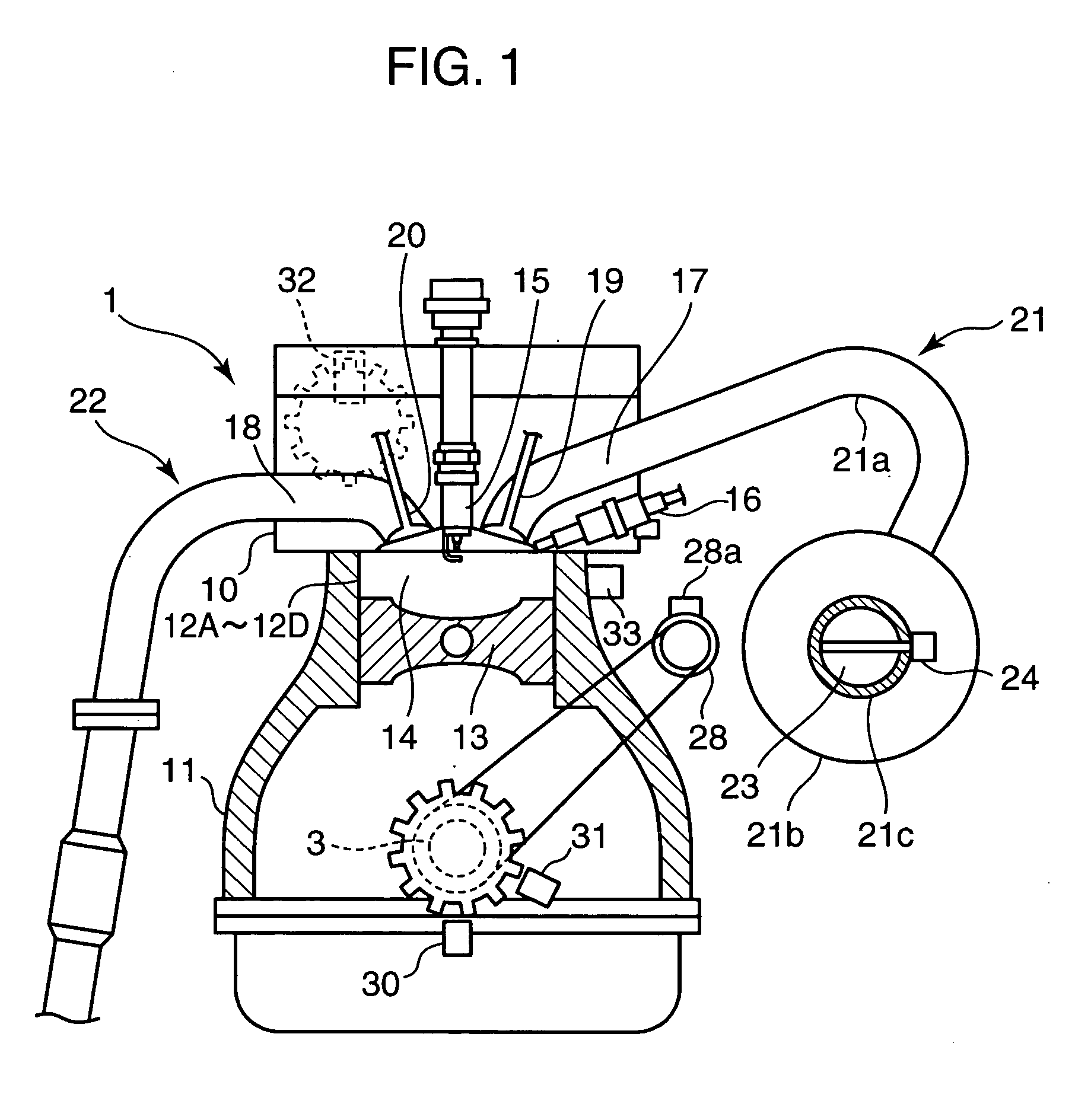
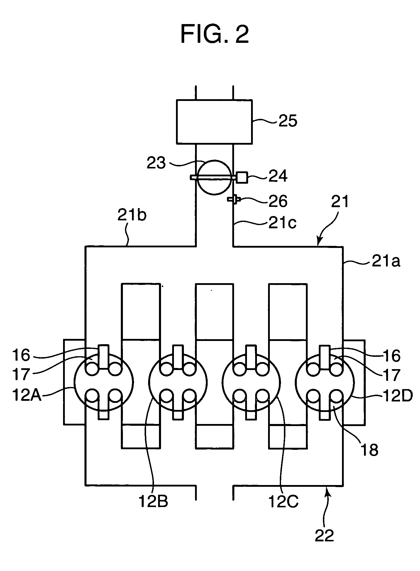
[0043]FIGS. 1 and 2 are diagrams generally showing the structure of a four-cycle spark ignition engine employing an engine starting system according to a first embodiment of the invention. This engine includes an engine body 1 having a cylinder head 10 and a cylinder block 11 and an electronic control unit (ECU) 2 (refer to FIG. 5) for performing overall engine control. The engine body 1 has a plurality of (four in the illustrated embodiment) cylinders 12A-12D, which may hereinafter be referred to as the first cylinder 12A, the second cylinder 12B, the third cylinder 12C and the fourth cylinder 12D, or simply as the cylinders 12 collectively. Pistons 13 connected to a crankshaft 3 by connecting rods are fitted in the individual cylinders 12A-12D whereby a combustion chamber 14 is formed above the piston 13 in each of the cylinders 12A-12D as shown in FIG. 1.

[0044] Disposed at the top of the combustion chamber 14 formed in each of the cylinders 12A-12D is a spark plug 15 with an ele...

second embodiment

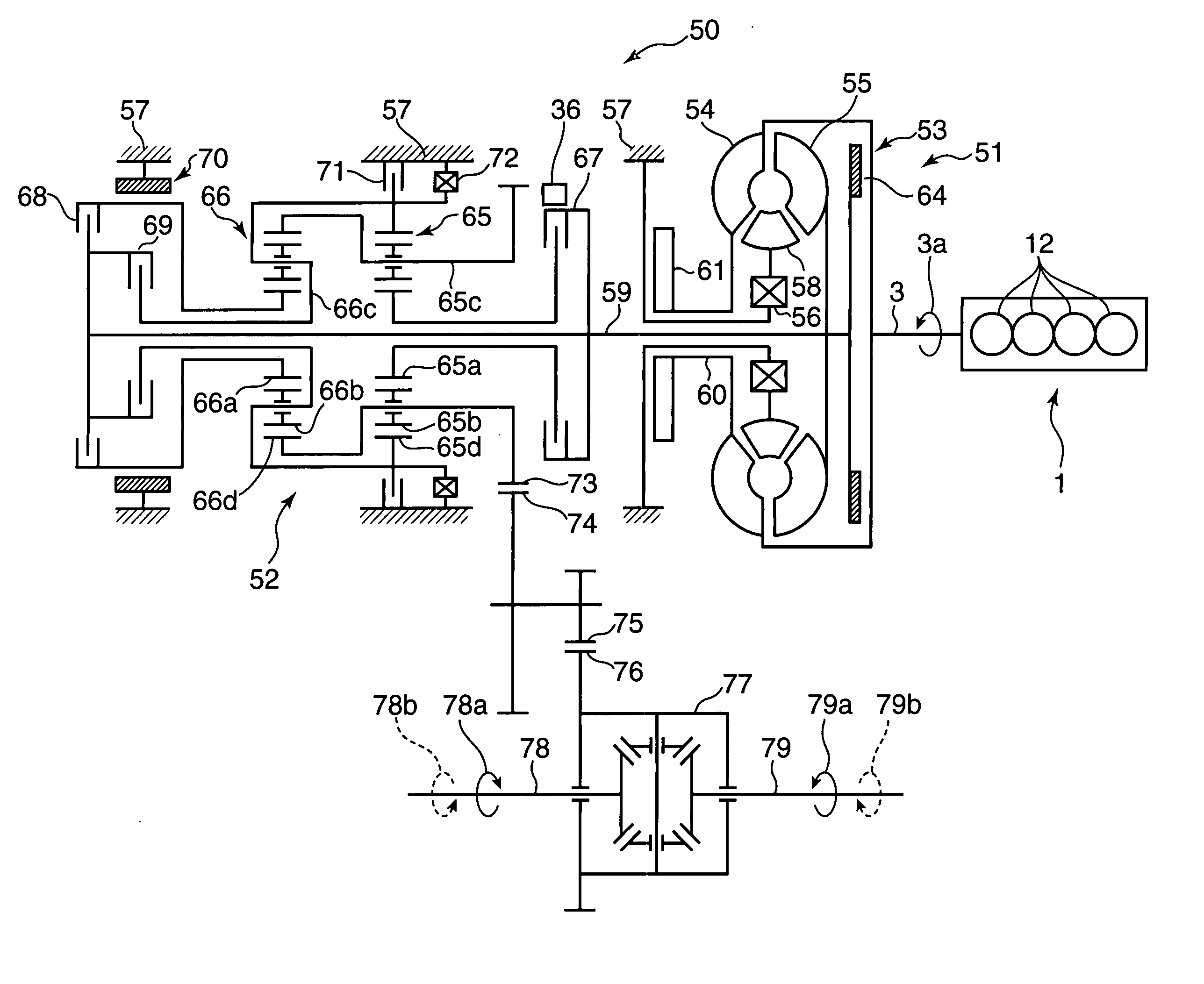
[0172] Now, an engine starting system according to a second embodiment of the invention is described. While a power train of the second embodiment has the same configuration as that of the first embodiment (FIG. 3), engine stop / restart control operation of the second embodiment slightly differs. The following discussion focuses on differences in the engine stop / restart control operation between the first and second embodiments.

[0173] In the foregoing first embodiment, the vehicle speed-related condition for the 3-2 shift defined as part of the idle stop conditions (automatic engine stop conditions) is that “the vehicle speed equals 19 km / h.” In the second embodiment, the vehicle speed-related condition for the 3-2 shift is that “the vehicle speed equals 0 km / h.”

[0174] According to the second embodiment, the engine stop / restart controller 2a controls the automatic transmission 50 such that the forward clutch 67 completes engagement during a period of initial engine reversing immedia...

third embodiment

[0201] Now, an engine starting system according to a third embodiment of the invention is described. While a power train of the third embodiment has the same configuration as those of the first and second embodiments (FIG. 3), engine stop / restart control operation of the third embodiment slightly differs. The following discussion focuses on differences between the engine stop / restart control operation performed in the third embodiment and that performed in the first and second embodiments.

[0202]FIG. 27 is a flowchart showing a third part of an engine stop / restart control operation subroutine used in the third embodiment corresponding to the flowchart of FIG. 25 used in the second embodiment. In the flowchart of FIG. 27, steps identical to those shown in FIG. 25 are designated by the same symbols and a detailed description of these steps is not provided in the following.

[0203] A substantial difference of the engine stop / restart control operation subroutine of the third embodiment f...


PUM


Abstract

An engine starting system for a power train including an engine and an automatic transmission includes an engine stop / restart controller. The automatic transmission having special mode includes first and second planetary gear sets having respective sun gears, a turbine shaft, an output gear, a forward clutch and a 2-4 brake. The forward clutch sets the automatic transmission in a drive condition when engaged and in a neutral condition when disengaged. If the special mode is selected under conditions where the output gear is locked, the sun gear of the first planetary gear set is locked. During execution of automatic engine stop control operation, the engine stop / restart controller causes the automatic transmission to initiate a transfer to the special mode before fuel supply is interrupted and causes the forward clutch to completely engage at a specific point in time after the automatic transmission has completed the transfer to the special mode.

Description

BACKGROUND OF THE INVENTION [0001] 1. Field of the Invention [0002] The present invention relates to an engine starting system for a power train which includes an engine and an automatic transmission for transmitting engine power while performing gear shifting operation in a prescribed manner, wherein the engine starting system is configured to automatically stop the engine when conditions for automatic engine stop are satisfied and to automatically restart the engine when conditions for engine restart are satisfied after automatic engine stop. [0003] 2. Description of the Related Art [0004] Developments in recent years in automotive industry intended for reducing fuel consumption and carbon dioxide (CO2) emissions provide an engine starting system which automatically stops the engine at idle and automatically restarts the engine when engine restart conditions are satisfied as a result of a driver's action taken after idle stop for starting a vehicle, for instance. [0005] Generally,...

Claims


Application Information

Patent Timeline
Patent Type & Authority Applications(United States)
IPC IPC(8): B60W10/00
CPCB60W10/06Y10T477/638B60W30/18018F02D41/042F02N11/0818F02N11/0844F02N19/00F02N99/002F02N2300/2006F16H61/0202F16H2061/0488Y02T10/48F16H2312/14Y10T477/679Y10T477/675B60W10/115Y02T10/40
Inventor NOBUMOTO, HIDETOSHISHOYA, TAIZOUUEDA, TAKAYUKIMAMIYA, KIYOTAKA
Owner MAZDA MOTOR CORP
Why Eureka
Try Eureka