Tunneler for use dual lumen tip catheter

a dual-lumen, catheter technology, applied in the direction of multi-lumen catheters, catheters, other medical devices, etc., can solve the problem of often complicating procedures caused by injuries to surrounding tissues

Inactive Publication Date: 2007-04-05
RADIUS INT PARTNERSHIP
View PDF2 Cites 40 Cited by
  • Summary
  • Abstract
  • Description
  • Claims
  • Application Information

AI Technical Summary

Problems solved by technology

The need to minimize injury to surrounding tissues often complicates the procedure for forming the tunnel.

Method used


Image

  • Tunneler for use dual lumen tip catheter
  • Tunneler for use dual lumen tip catheter
  • Tunneler for use dual lumen tip catheter

Examples


Embodiment Construction

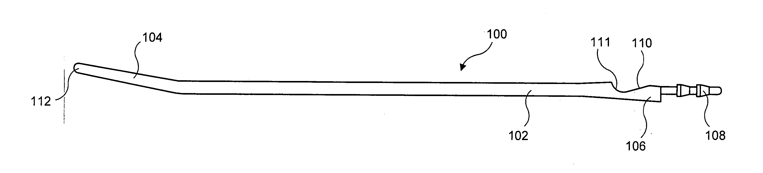
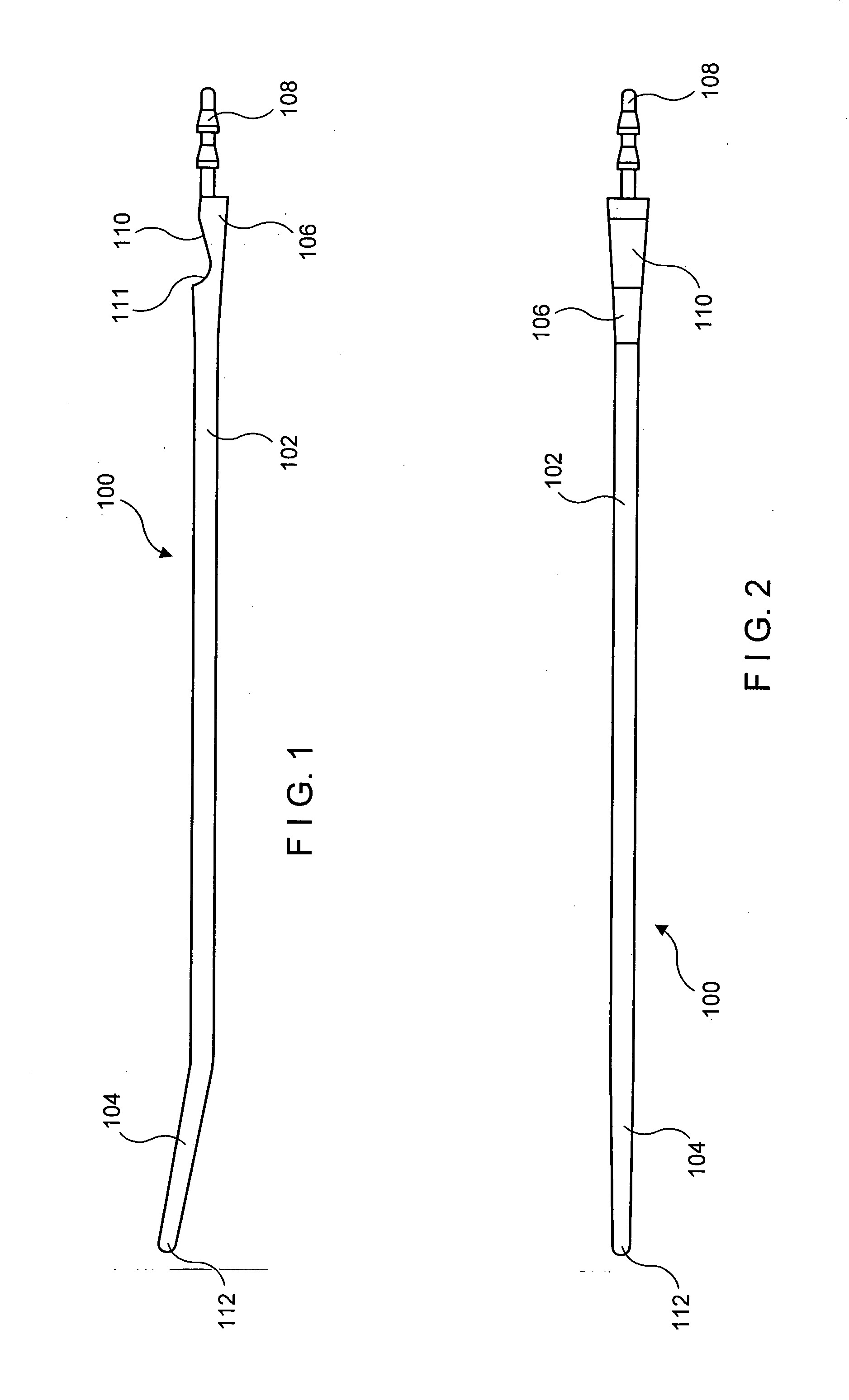
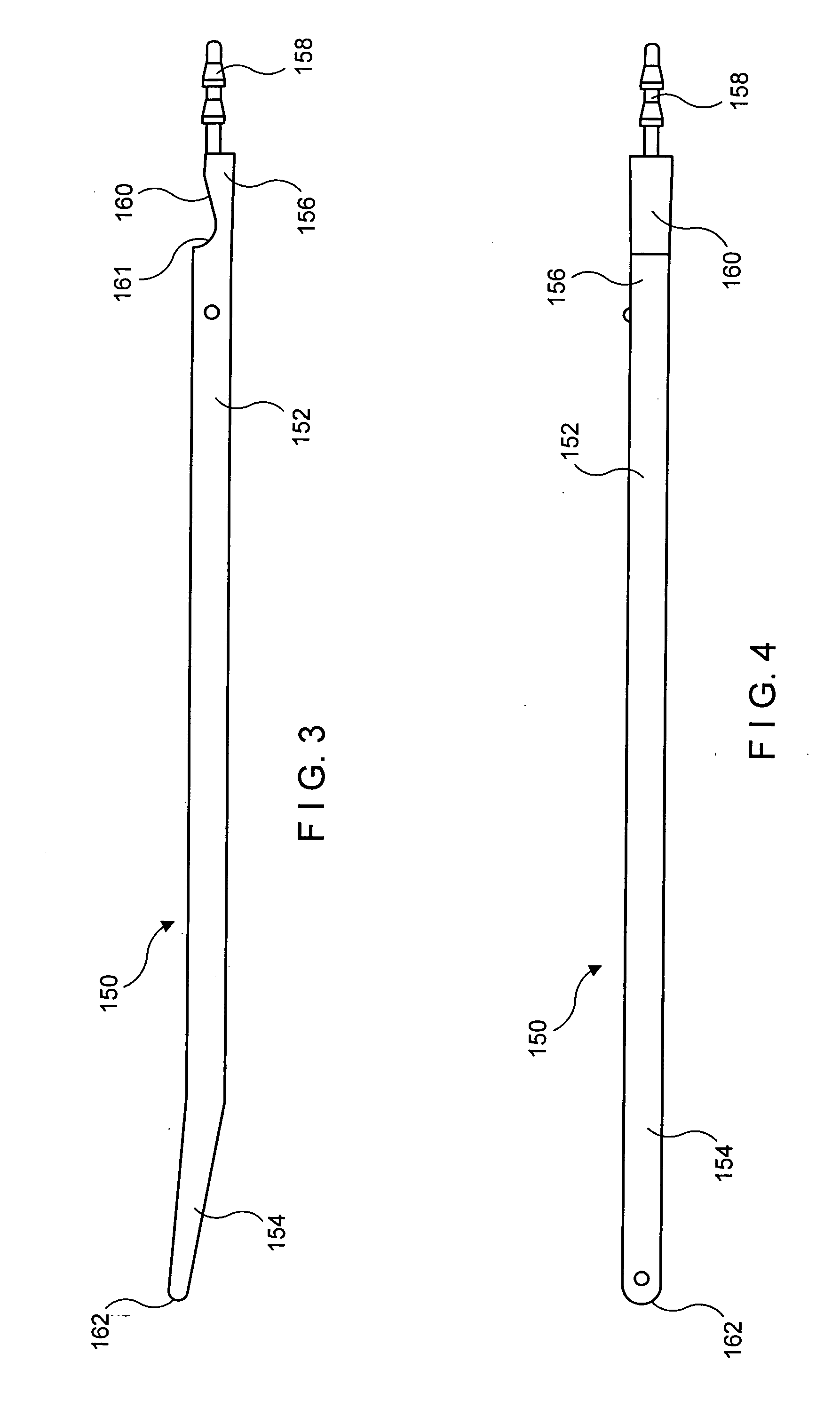
[0018] The present invention may be further understood with reference to the following description and the appended drawings, wherein like elements are referred to with the same reference numerals. The invention is related to tunneler devices used in conjunction with devices used to introduce and / or remove therapeutic compounds from the body. More specifically, the invention is related to a novel construction for a catheter having a dual lumen tip.

[0019] Catheters are basically flexible tubes formed by an outer shell which defines an inner lumen which may serve as a fluid conduit. Various fittings or connections may be used at the proximal end to connect the catheter to one or more additional devices. The outer shell is typically formed of a material selected to be impermeable to the fluid flowing therein with the length and diameter of the catheters varying considerably depending on the application. Generally, catheters are formed of flexible, biocompatible materials (e.g., polyme...


PUM


Abstract

A tunneler for a dual lumen tip catheter, comprises an elongated body extending from a distal tissue-penetrating end to a proximal, catheter-coupling end, the catheter coupling end including a catheter tip receiving portion including a cutout sized and shaped to receive a dual lumen tip of a catheter to be coupled thereto and a proximally extending lumen-mating projection oriented so that, when inserted into a lumen of the catheter, the dual lumen tip of the catheter is received in the cutout in an orientation relative to an elongated body of the catheter substantially the same as when the dual lumen tip and the elongated body of the catheter are in an unstressed state.

Description

BACKGROUND OF THE INVENTION [0001] Catheters are routinely used to form a semi-permanent path into the body through which fluids can pass to and from target sites eliminating the need for repeated insertions of needles, etc. [0002] Some vascular catheters, such as peripherally inserted central catheters (PICC's) and dialysis catheters are not generally inserted through the skin at locations adjacent to the site of entry into a target blood vessel. Instead, a tunnel is formed under the skin between a location at which the catheter enters a target blood vessel and a location at which the catheter penetrates the skin. The length of the tunnel connecting the two locations may differ depending on the purpose of the catheter and the anatomy of the patient. [0003] The need to minimize injury to surrounding tissues often complicates the procedure for forming the tunnel. Because the ends of these catheters are typically too large to form the tunnel without excessive trauma, a separate device...

Claims


Application Information

Patent Timeline
Patent Type & Authority Applications(United States)
IPC IPC(8): A61M5/178
CPCA61B17/3415A61M25/00A61M25/0194A61M39/0247A61M2025/0031A61M2025/0037
Inventor FEELEY, KRISTINQUINN, DAVID G.
Owner RADIUS INT PARTNERSHIP
Why Eureka
Try Eureka