Method of providing non-uniform stator vane spacing in a compressor

Inactive Publication Date: 2007-04-12
GENERAL ELECTRIC CO
View PDF27 Cites 16 Cited by
  • Summary
  • Abstract
  • Description
  • Claims
  • Application Information

AI Technical Summary

Benefits of technology

[0005] In accordance with a preferred aspect of the present invention, there is provided a method of installing stator vanes in the field which enables a change of blade counts in the upper half of the compressor casing permitting compressors in situ or in the field to be upgraded to compressors with non-uniform upper and lower compressor casing blade counts to reduce the vibratory response of the rotating blades. For example, for a particular compressor in the field with a given count of stator vanes, the adjacent stator stages in the upper half of the compressor casing are provided increased stator blade counts, e.g., 26/23 for S0 and 24/23 for S1 yielding blade counts of forty-nine for the S0 sta

Problems solved by technology

These pulses induce a vibratory response in the rotating blade which can be deleterious to the rotating blade causing failure due to high cycle fatigue.
However, because of the vibratory responses of the rotating blades, non-uniform vane spacings between upper and

Method used


Image

  • Method of providing non-uniform stator vane spacing in a compressor
  • Method of providing non-uniform stator vane spacing in a compressor
  • Method of providing non-uniform stator vane spacing in a compressor

Examples


Embodiment Construction

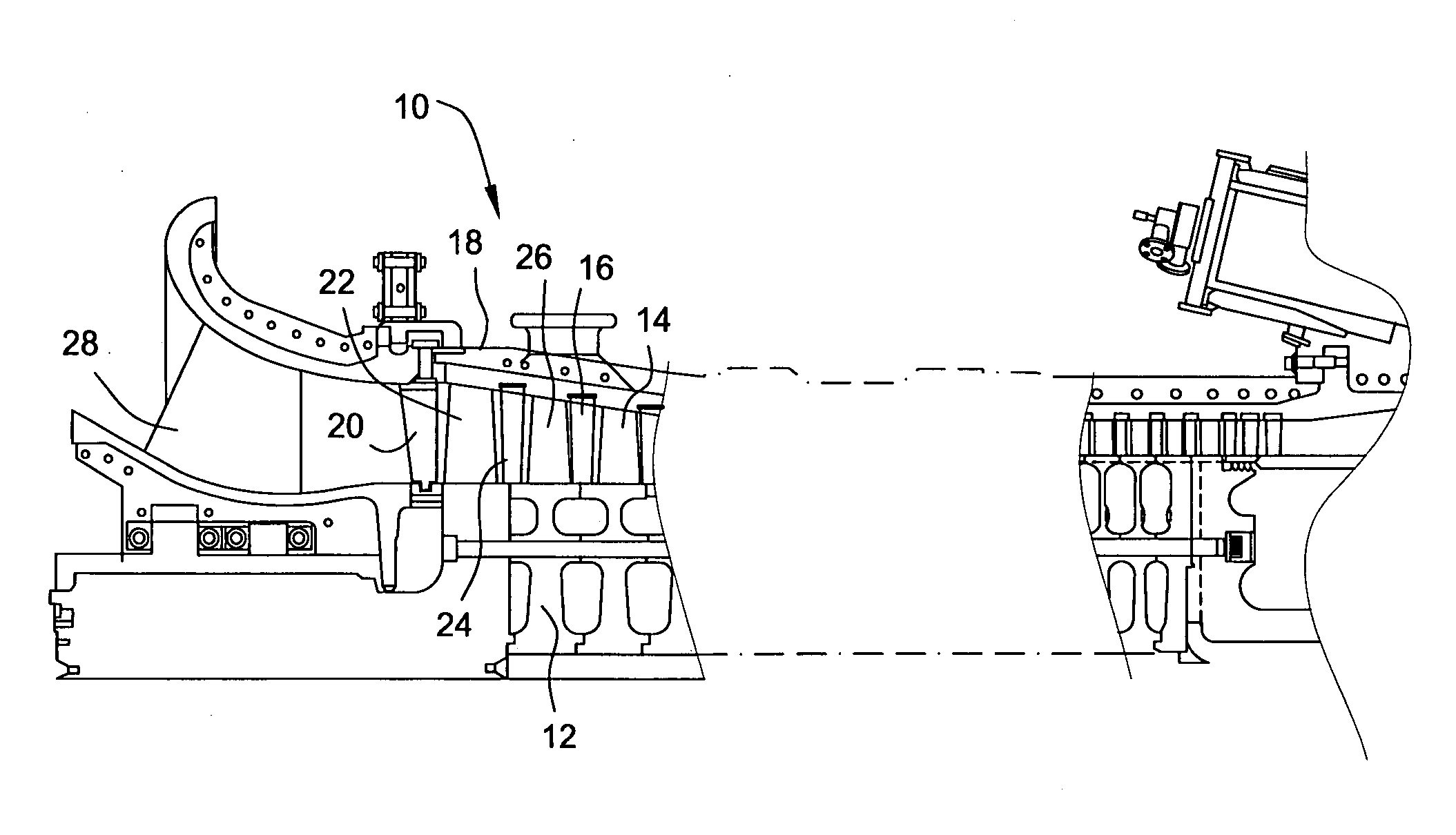
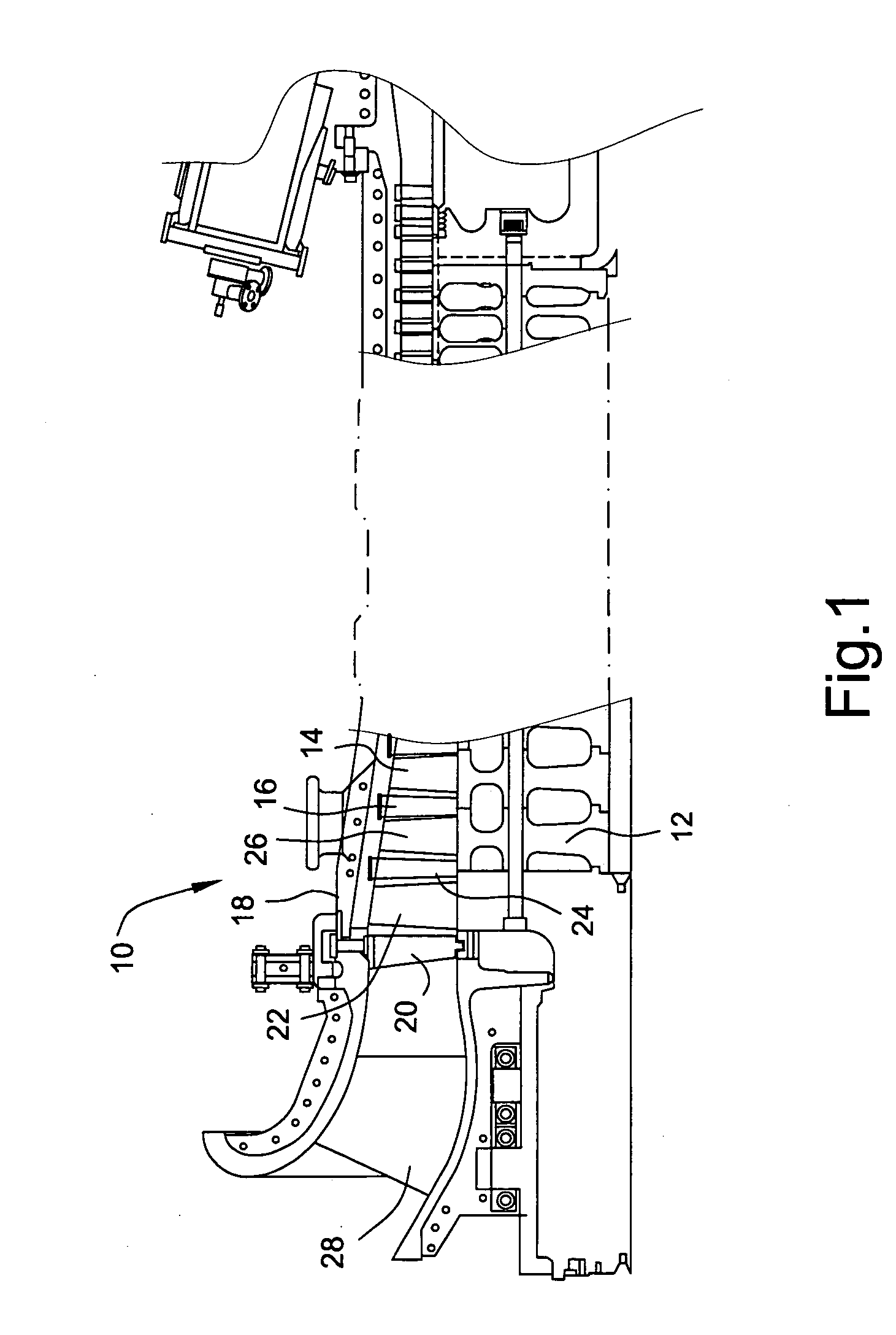
[0011] Referring to FIG. 1, there is illustrated an upper half of a compressor generally designated 10. Compressor 10 includes a rotor 12 mounting buckets or blades 14 for rotation about the axis of the compressor and stator vanes 16 fixed to the upper casing half 18. It will be appreciated that the vanes 14 of the rotor are circumferentially spaced one from the other about the rotor axis and that the stator vanes 16 are similarly circumferentially spaced one from the other about the axis. The vanes and buckets form various stages of the compressor. For example, the vanes 20 and buckets 22 form compressor stage S0 while the vanes 24 and buckets 26 form stage S1. Inlet guide vanes 28 are also illustrated in FIG. 1.

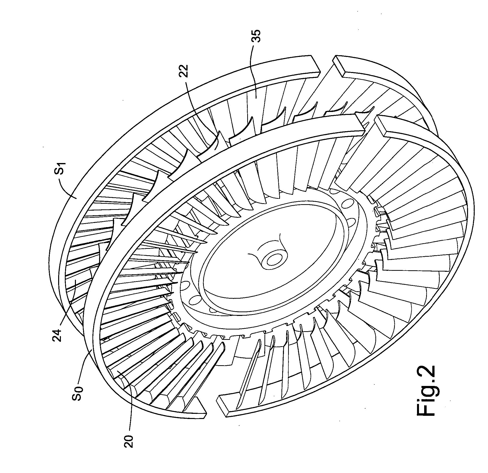
[0012] Referring to FIG. 2, there is schematically illustrated the stator vanes 20 of stage S0 and the stator vanes 24 of stage S1. The buckets 22 mounted on the rotor 12 are illustrated disposed between the stator vanes 20 and 24. The stator vanes 20 and 24 as well as sta...


PUM


Abstract

Stator blade counts of an upper compressor casing for adjacent stages S0 and S1 are changed in the field to provide additional stator vanes and hence an increased vane count. Particularly, the upper casing half of the compressor is removed from the lower casing half. The original stator vanes on opposite axial sides of the first stage buckets are removed from the upper casing half and replaced by an additional sets of stator vanes providing a non-uniform vane spacing as between the upper and lower halves of the compressor as well as between axially adjacent stages S0 and S1. The unequal vane counts reduce the vibratory response of the rotating blades between stages S0 and S1.

Description

[0001] The present invention relates to non-uniform stator vane spacing in a compressor and particularly relates to non-uniform blade counts of stator vanes in the upper and lower compressor casing halves of a compressor stage to minimize or eliminate vibratory response of adjacent rotating blades. BACKGROUND OF THE INVENTION [0002] In axial flow compressors, stator vanes alternate with rotating blades or buckets in the various stages of the compressor. The stator vanes are circumferentially spaced one from the other about the compressor axis and are secured to the upper and lower compressor casing halves. The upper and lower casing halves are joined one to the other at the compressor midline and provide a complete circumferential array of stator vanes for each compressor stage. As each rotating blade mounted on the rotor completes each revolution at a given rotational velocity, the rotating blade receives aerodynamic excitation pulses from each stator vane. This pulse can be genera...

Claims


Application Information

Patent Timeline
IPC IPC(8): B21K21/16B23P15/00
CPCF01D9/041F04D29/542F04D29/666F04D29/667F05D2230/80F05D2260/961Y10T29/4973Y10T29/49732Y10T29/49236Y10T29/49238Y10T29/49318Y10T29/49716Y10T29/49321
Inventor GAUTREAU, JAMES C.WASSYNGER, STEPHEN P.
Owner GENERAL ELECTRIC CO
Why Eureka
Try Eureka