Bearing health monitor

a technology of bearing health monitor and monitor, which is applied in the direction of vibration measurement in solids, machine part testing, liquid fuel engine components, etc., can solve the problems of excessive rotor speed, bearing wear that affects the service life of turbocharger, and bearing wear that can be exacerbated

Inactive Publication Date: 2007-04-12
HONEYWELL INT INC
View PDF32 Cites 34 Cited by
  • Summary
  • Abstract
  • Description
  • Claims
  • Application Information

AI Technical Summary

Benefits of technology

[0005] In various embodiments, the present invention solves some or all of the needs mentioned above, providing a turbocharger bearing wear monitor that can provide information on the condition of a turbocharger.

Problems solved by technology

Bearing wear significantly affects the turbocharger's service life.
Bearing wear can be exacerbated by a variety of conditions, including fuel or particulate contaminants in oil used to lubricate the turbocharger, excessive rotor speeds, and excessive operating temperatures.
When bearing wear exceeds an acceptable level, compressor or turbine blades may come in to contact with their respective housings, leading to catastrophic failure.
Such failures can lead to failure of the related internal combustion engine, oil discharges—either externally or into other systems, and possibly even engine fires.

Method used


Image

  • Bearing health monitor
  • Bearing health monitor
  • Bearing health monitor

Examples


first embodiment

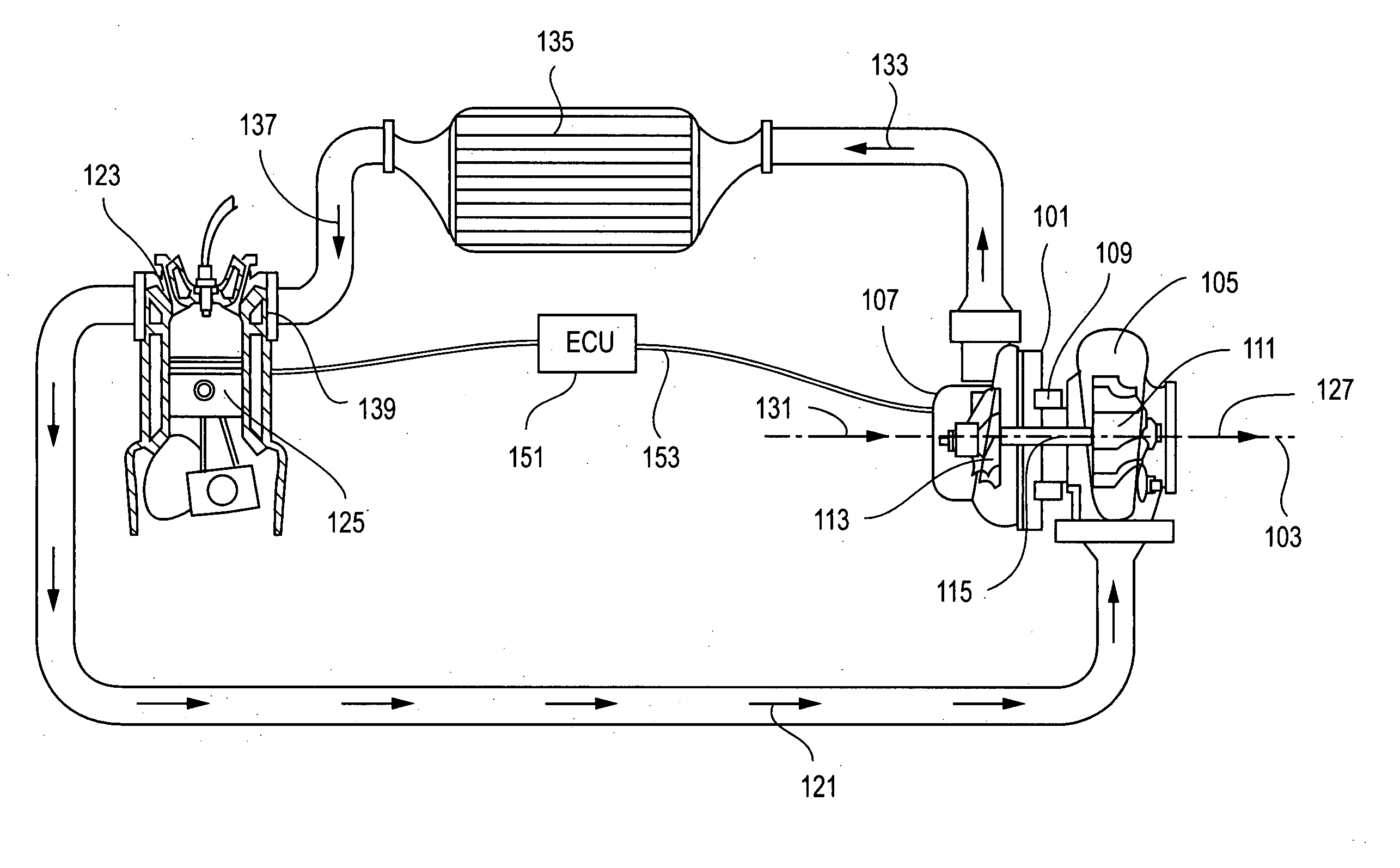
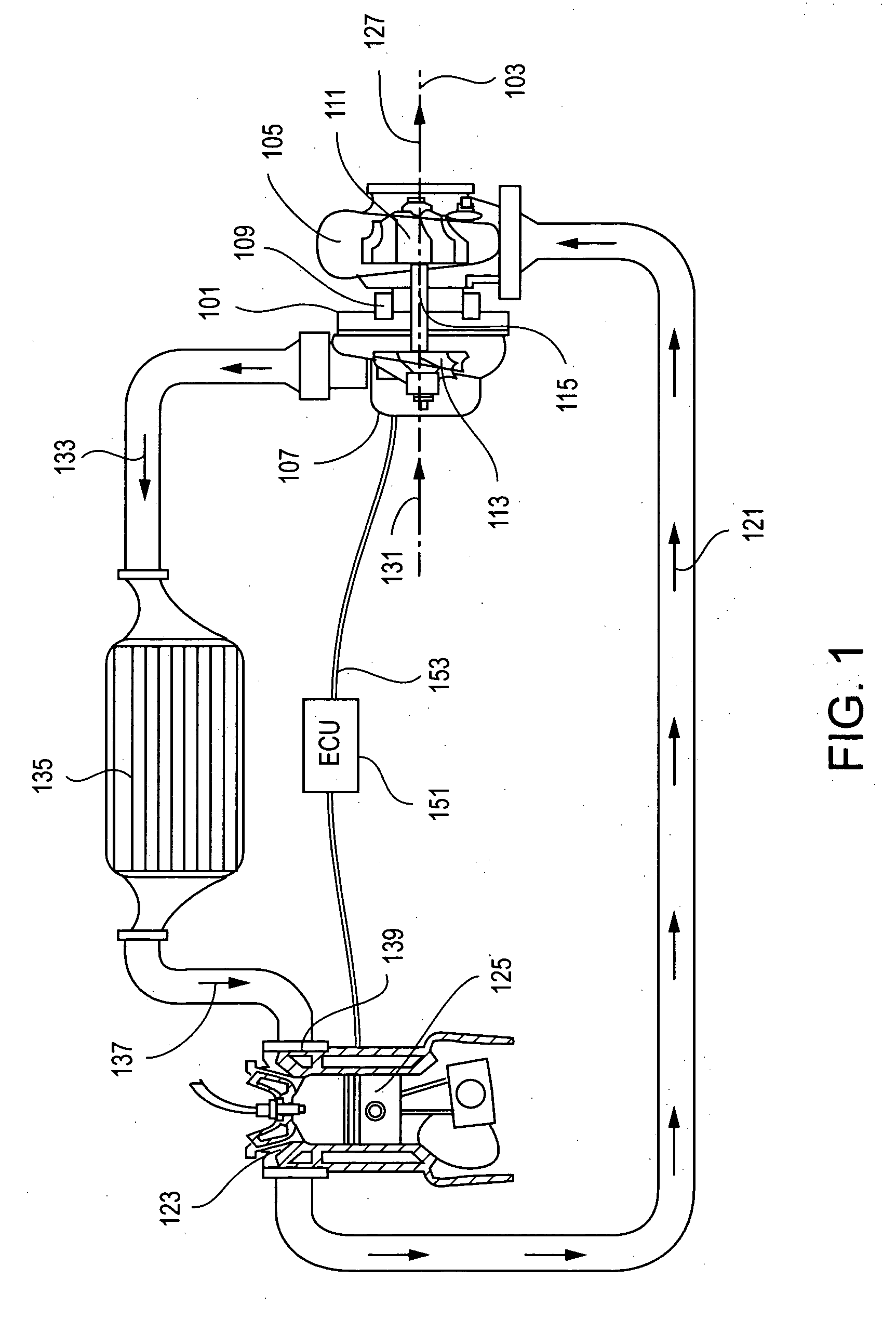
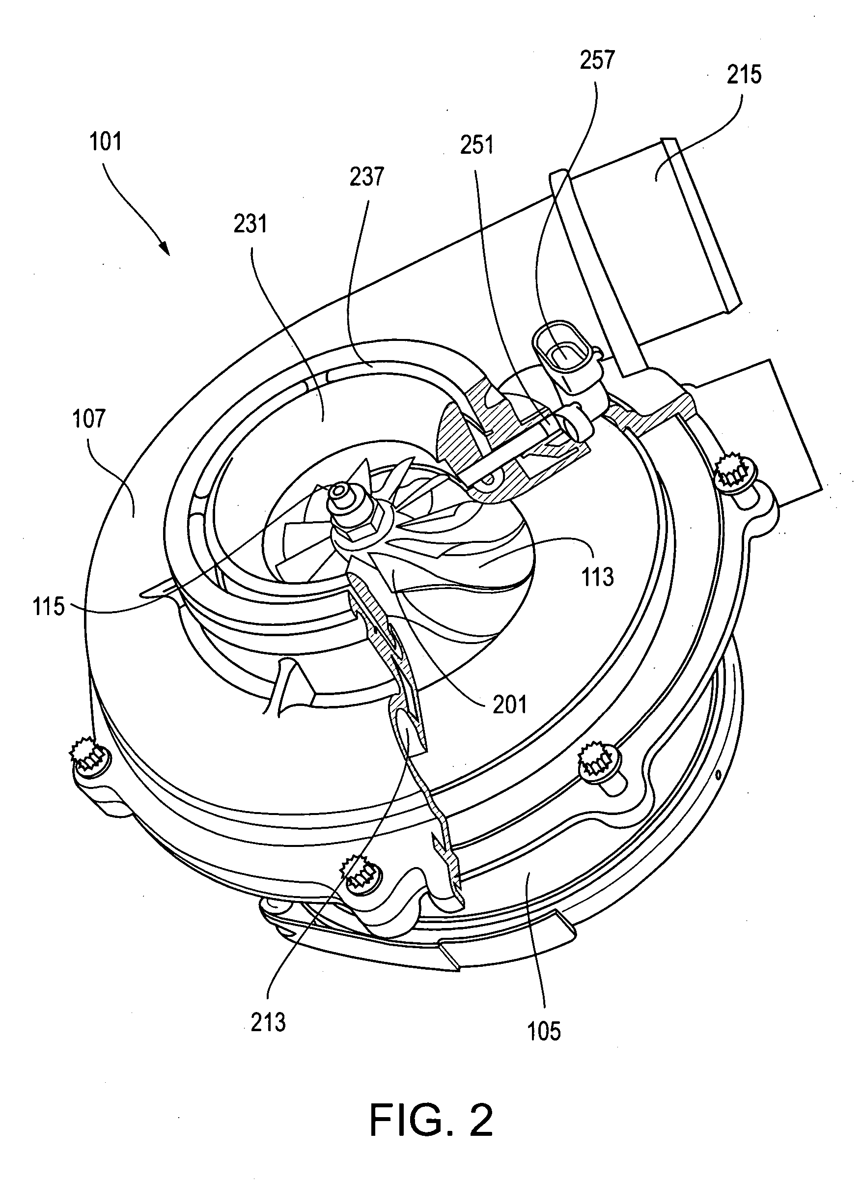
[0015] With reference to FIGS. 1 and 2, in the invention, a turbocharger 101 includes a turbocharger housing, a rotor configured to rotate within the turbocharger housing along an axis of rotor rotation 103, axial bearings and journal bearings. The turbocharger housing includes a turbine housing 105, a compressor housing 107, and a bearing housing 109 that connects the turbine housing to the compressor housing.

[0016] The rotor includes a turbine wheel 111 located substantially within the turbine housing, a compressor wheel 113 located substantially within the compressor housing, and a shaft 115 extending along the axis of rotor rotation, through the bearing housing, to connect the turbine wheel to the compressor wheel. The journal bearings (not shown) are at two locations within the bearing housing, and are configured to restrict the shaft (and thus the rotor) from rotating or translating off the axis of rotor rotation. The axial bearing (not shown) is within the bearing housing, an...

second embodiment

[0035] With reference to FIG. 5, the invention is configured similar to the first, except for the position, orientation and design of the blade sensor. This embodiment includes a blade sensor 401 having a sensor element 403 positioned such that, through a sensing surface 405, it detects the passage of an outer-edge portion 407 of each detectable blade 409. The sensor element is oriented to detect blade distance in a direction substantially normal to the direction in which the outer edge extends. The outer-edge portion extends in a direction substantially between being normal to, and being parallel to, the axis of rotor rotation (e.g., angled between 30 and 60 degrees from the axis), such that the blade sensor is sensitive to rotor translation, rotation or bending that causes the compressor wheel to translate in a radial and / or an axial direction.

[0036] Other embodiments may be configured with sensors positioned and oriented to sense rotor movement, with respect to the turbocharger h...


PUM


Abstract

A turbocharger monitor including a sensor adapted and positioned with respect to a turbocharger housing to sense passing compressor blades, generating both rotor rotation information and rotor displacement information. A controller is configured to receive the generated information from the blade sensor, and to establish rotor rotation speed and an indicator of bearing condition.

Description

[0001] The present invention relates generally to turbomachinery and, more particularly, to apparatus and methods of monitoring the condition of turbocharger bearings. BACKGROUND OF THE INVENTION [0002] Turbochargers may be used with internal combustion engines to increase the available power from a given size of engine. In use, turbochargers experience a wide array of operating conditions, through a wide array of parameters such as operating speed, temperature, engine backpressure, oil pressure, oil quality, and the like. Depending upon the operating conditions experienced by a given turbocharger, its service life may vary significantly from that expected. [0003] Bearing wear significantly affects the turbocharger's service life. Bearing wear can be exacerbated by a variety of conditions, including fuel or particulate contaminants in oil used to lubricate the turbocharger, excessive rotor speeds, and excessive operating temperatures. When bearing wear exceeds an acceptable level, c...

Claims


Application Information

Patent Timeline
Patent Type & Authority Applications(United States)
IPC IPC(8): F02D23/00
CPCF01D21/003F01D25/16F02B39/16F05D2220/40F05D2270/304F05D2270/301F05D2270/42F16C2360/24
Inventor GREENTREE, CHRISTOPHER
Owner HONEYWELL INT INC
Why Eureka
Try Eureka