
Plastic heddle

a plastic heddle and heddle technology, applied in the field of plastic heddles, can solve the problems of limiting the configuration of the heddle, increasing the cost of the heddle, and heddles made from such plastics are more fragile than the metal heddles, and achieves the effects of high rigidity, strength, and durability

Inactive Publication Date: 2007-04-12
GTP GREENVILLE INC
View PDF28 Cites 19 Cited by
  • Summary
  • Abstract
  • Description
  • Claims
  • Application Information

AI Technical Summary

Benefits of technology

[0007] It is therefore a principal object of the present invention to provide a molded heddle which does not require extensive machining or polishing while providing enough rigidity, strength, and durability within the size limitations and tolerances needed for the heddle's use within a weaving machine and with automatic drawing-in machines.
[0008] It is another object of the present invention to provide a heddle that reduces the wear within the rod slots as well as within the yarn eye of the heddle over extended use as compared to commonly used plastic heddles.
[0010] It is yet another object of the invention to provide a heddle having an increased contact surface within the yarn eye that supports the warp yarn passing therethrough to decrease damage caused to warp yarn during the weaving operation.
[0011] It is a further object of the invention to provide a rod slot for a plastic heddle that increases the ease of installation of the heddle on a rod of a harness frame, while securely holding the heddle to the rods of the harness frame.

Problems solved by technology

However, the metal heddles are limited by the fact that they are usually stamped or soldered, thereby limiting the configurations the heddles may possess.
The use of metal as material and the handling involved in preparing the metal heddles increases the cost of the heddles.
However, due to the size and tolerance limitations needed for the use of heddles in weaving machines, the heddles made from such plastics are more flimsy than the metal heddles.
Such heddles also wear quickly where the warp yarns come in contact with the walls of the yarn eye.
Such wearing within the yarn eye can be especially detrimental by creating a greater opportunity to damage the yarn during the weaving process.
Heretofore, the plastic heddles have seen limited use, because the plastic heddles cannot obtain enough rigidity, strength and durability to perform as well as metal heddles.

Method used


Image

  • Plastic heddle
  • Plastic heddle
  • Plastic heddle

Examples


Embodiment Construction

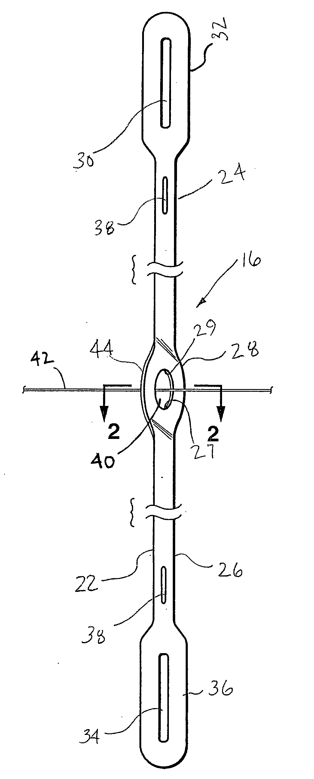
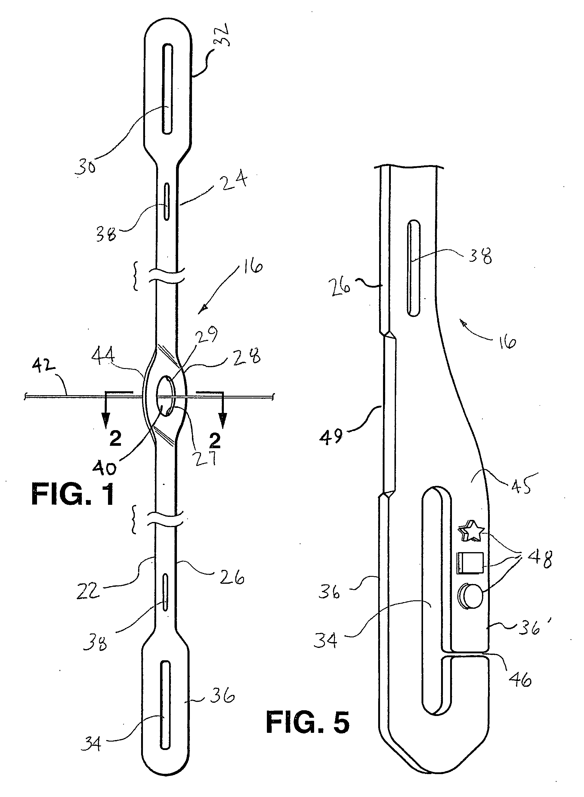
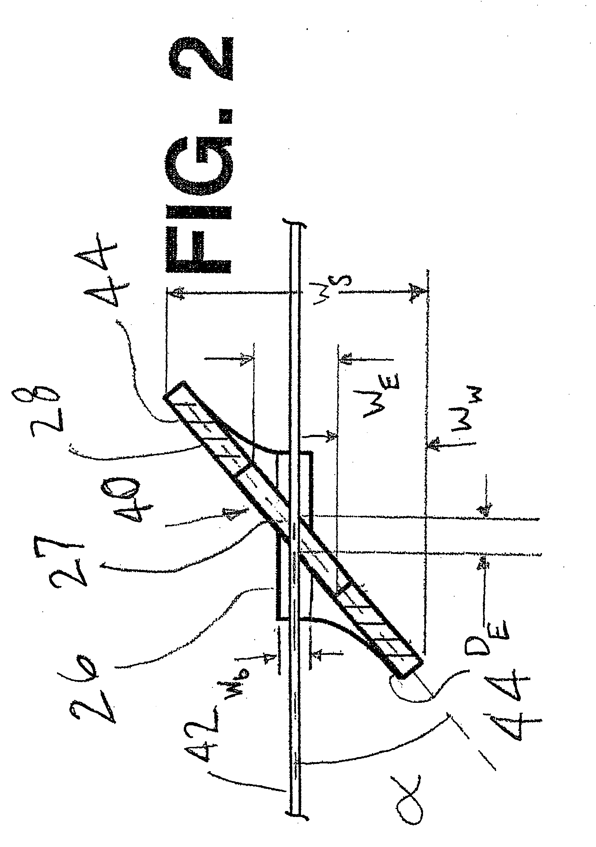
[0030] Reference will now be made in detail to the presently preferred embodiments of the invention, one or more examples of which are illustrated in the accompanying drawings. Each example is provided by way of explanation of the invention, which is not restricted to the specifics of the example. In fact, it will be apparent to those skilled in the art that various modifications and variations can be made in the present invention without departing from the scope of spirit of the invention. For instance, features illustrated or described as part of one embodiment, can be used in another embodiment to yield a still further another embodiment. Thus, it is intended that the present invention cover such modifications and variations as come within the scope of the appended claims and their equivalents. The same numerals are assigned to the same components throughout the drawings and description.

[0031]FIG. 8 illustrates a harness frame for use within a weaving machine. In general, harnes...


PUM


Abstract

Heddles for use within a harness frame of a weaving machine are provided. Each of the heddles includes a body formed from a liquid crystal polymer resin. The body forms at least one rod slot enabling engagement with a harness frame. The body also has an eyelet section with the eyelet section forming a yarn eye through which a yarn is capable of passing.

Description

CROSS-REFERENCE TO RELATED APPLICATIONS [0001] N / A STATEMENT REGARDING FEDERALLY SPONSORED RESEARCH OR DEVELOPMENT [0002] N / A BACKGROUND [0003] The invention relates to a plastic heddle and, in particular, heddles molded from liquid crystal polymer resins. [0004] Heddles used within harness frames serve the purpose of controlling warp yarns in weaving machines. The warp yarns run through yarn eyes that are positioned intermediate of the ends of the respective heddles. As is commonly understood, a single warp yarn passes through the yarn eye of the heddle. The raising and lowering of different harness frames in which the heddles reside form sheds within a weaving machine to allow insertion of filling yarns to weave a fabric. The heddles are typically mounted on a support bar of a harness frame within the weaving machine. In this manner, the depth, or flat strip side, of the heddle is parallel to the direction of travel of the warp yarn. The eye of the heddle is typically rectangular ...

Claims


Application Information

Patent Timeline
IPC IPC(8): D03C9/00
CPCD03C9/02D03C9/024
Inventor KORBUTT, THOMAS A.FAASSE, GENE E.KRAMER, CHARLES F.PERRY, JOHN F.NEEL, JOSEPH PATRICK
Owner GTP GREENVILLE INC
Learn More