
Flow path splitter duct

a splitter and flow path technology, applied in the field of aeronautical vehicle systems, can solve the problems of loss of efficiency through the nozzle, a potential loss of engine control, loss of efficiency and engine control situation,

Active Publication Date: 2007-04-12
THE BOEING CO
View PDF20 Cites 11 Cited by
  • Summary
  • Abstract
  • Description
  • Claims
  • Application Information

AI Technical Summary

Benefits of technology

[0007] The present invention has several advantages over existing VTOL aircraft. One advantage of the present invention is that the aircraft may use ducted engine exhaust gas that passes through one of the primary flow ducts through the main rotor mast to turn the rotor hub and blade when less than all of the engines are operational.
[0008] Another advantage of the present invention is that it provides configuration versatility for various applications having differing performance requirements.
[0009] Furthermore, the present invention is a key component that allows multiple engines or engine sets to have a separate gas path that may eliminate the engine control engine out problem should the 1-engine out situation occur.
[0010] Moreover, the “Dual” flow path splitter duct may direct the gas from the coaxial mast duct and into the rotor blade interface fitting.

Problems solved by technology

While the ducted passageways may provide for the increase in engine exhaust gas produced by the multiple engines, there becomes a loss of efficiency through the nozzles and a potential loss of engine control when the CRW experiences a loss of engine or engine out.
The loss of efficiency and engine control situation may also occur when less than all of the engines are operating while the CRW is in helicopter mode.

Method used


Image

  • Flow path splitter duct
  • Flow path splitter duct
  • Flow path splitter duct

Examples


Embodiment Construction

[0020] In each of the following figures, the same reference numerals are used to refer to the same components. While the present invention is described with respect to an article, assembly and method for providing directed fluid propulsion used for lift in a dual-mode aircraft having a vertical lift mode and a fixed wing mode of flight, the present invention may be adapted for various applications and systems known in the art.

[0021] In the following description, various operating parameters and components are described for one embodiment. These specific parameters and components are included as examples and are not meant to be limiting. Another embodiment is also presented to illustrate the breadth of the present invention.

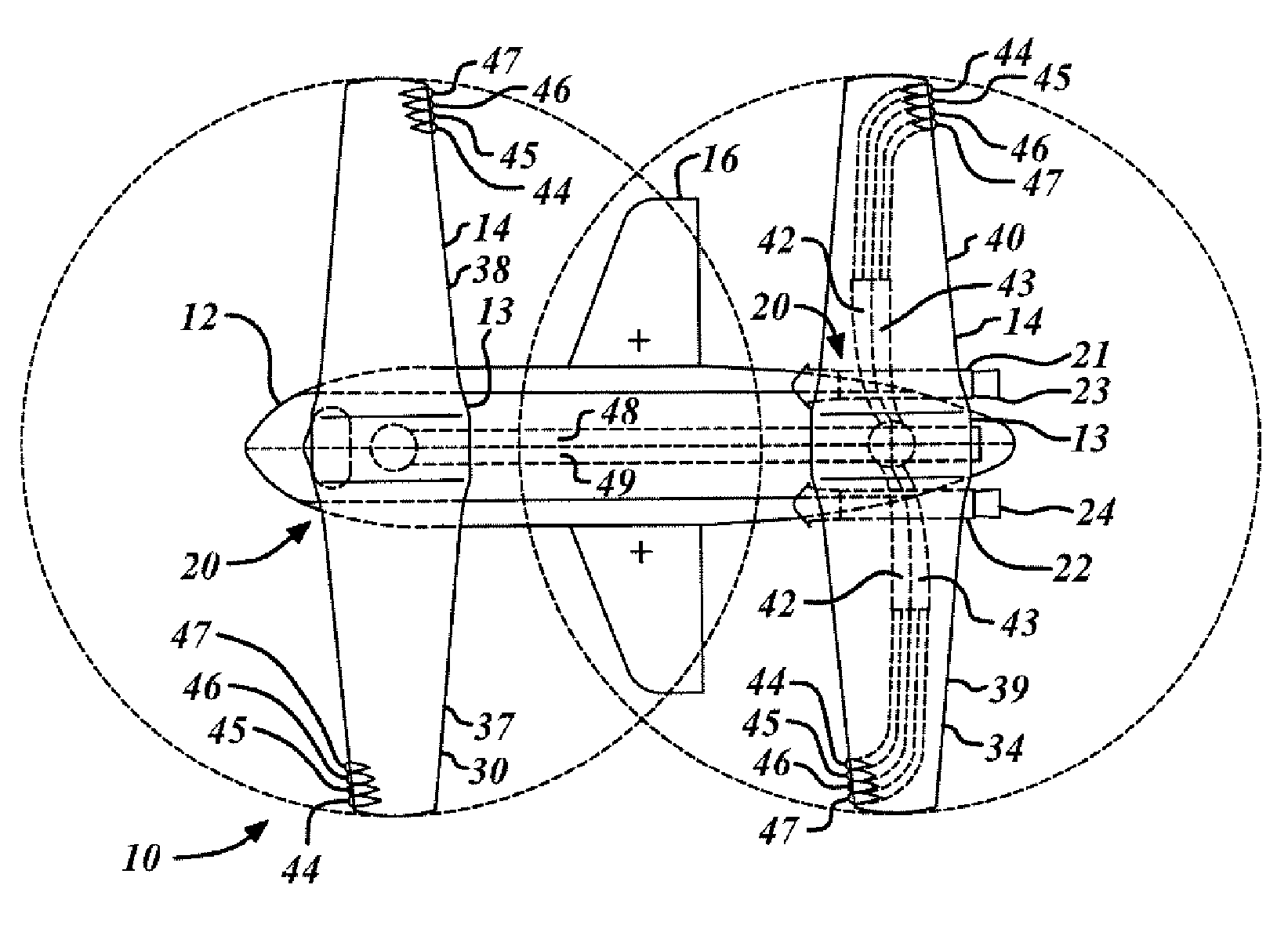
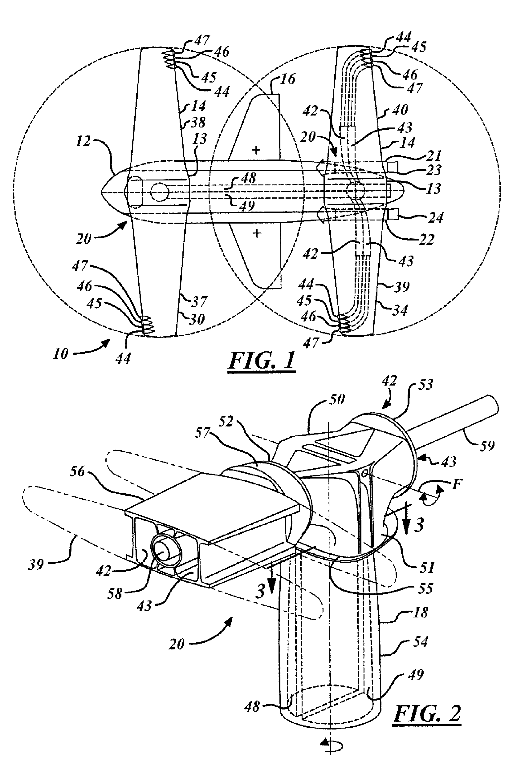
[0022]FIG. 1 shows a top view of a vertical takeoff and landing (VTOL) aircraft 10 utilizing a tandem rotor / wing configuration in accordance with an embodiment of the present invention. The aircraft 10 includes a fuselage 12, multiple rotor / wing hub assemblies 1...


PUM


Abstract

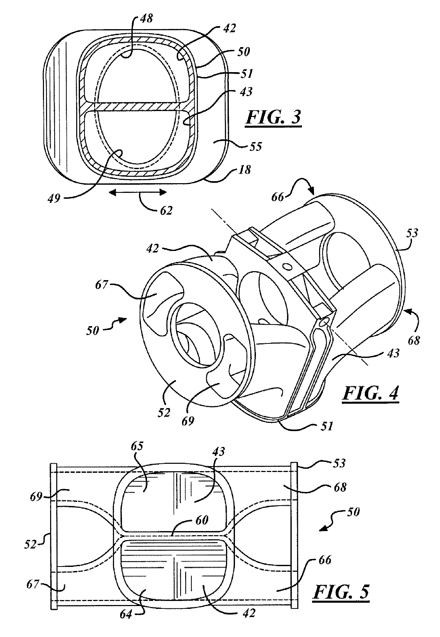
A flow path splitter duct is provided. The flow path splitter duct includes a main hub, a first outlet hub and a second outlet hub. The main hub has a plurality of inlet ports each being separated by at least one wall. The first outlet hub has a plurality of first duct outlet ports, each of the first duct outlet ports are in fluid communication with only one of the corresponding plurality of inlet ports. The second outlet hub has a plurality of second duct outlet ports, each of the second duct outlet ports are in fluid communication with only one of the corresponding plurality of inlet ports, wherein engine exhaust gas that enters one of the plurality of inlet ports is simultaneously diverted to only one of the first duct outlet ports and to only one of the second duct outlet ports. A vertical takeoff and landing aircraft is also provided that includes the flow path splitter duct. A method of using the same is also provided.

Description

TECHNICAL FIELD [0001] The present invention relates generally to aeronautical vehicle systems, and more particularly, to an article, system and method for providing directed fluid propulsion used for lift in a dual-mode aircraft having a vertical lift mode and a fixed wing mode of flight. BACKGROUND OF THE INVENTION [0002] In order to have vertical takeoff and landing capability of a helicopter and to have forward flight speed ability of another aircraft, different styles of vertical takeoff and landing (VTOL) aircraft are being introduced and becoming more abundant. One aircraft is the canard rotor / wing design. The canard rotor / wing (CRW) design typically includes a single wing centrally located or two offset wings located on an aircraft fuselage that may be operated in a helicopter mode and in a fixed wing mode. Each wing includes two symmetrical blades that operate irrespective of flow direction. In helicopter mode the wing of the CRW spins the rotor. In fixed wing mode the wing...

Claims


Application Information

Patent Timeline
Patent Type & Authority Applications(United States)
IPC IPC(8): B64C15/02
CPCB64C15/02B64C29/0066
Inventor MUYLAERT, NEAL W.
Owner THE BOEING CO
Learn More