Surface pressure load device of slide valve
- Summary
- Abstract
- Description
- Claims
- Application Information
AI Technical Summary
Benefits of technology
Problems solved by technology
Method used
Image

Examples
embodiment 1
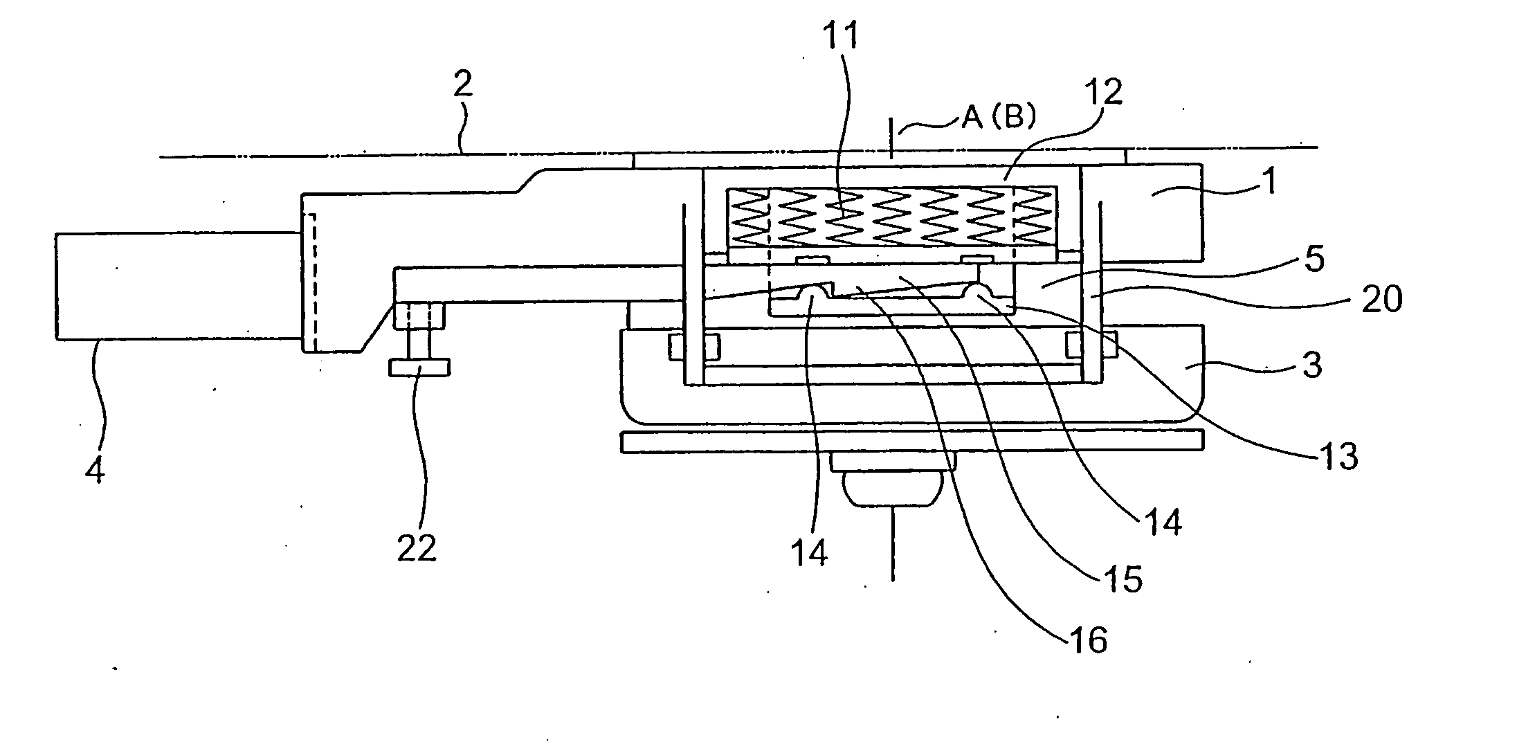
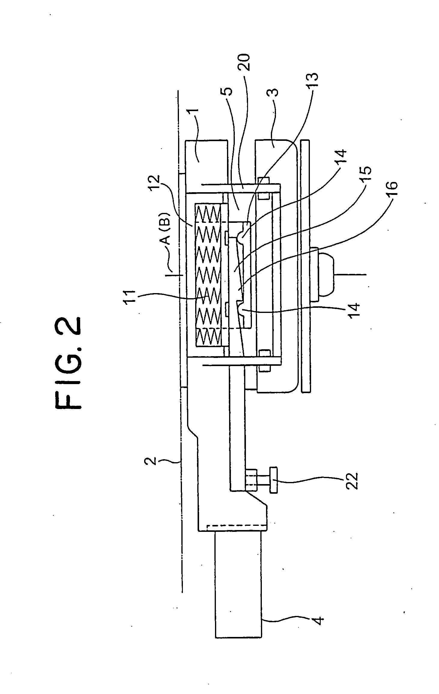
[0022] Embodiment 1
[0023] Reference numeral 1 of FIGS. 1 and 2 denotes a housing that is fixed to a bottom surface of a molten metal vessel 2 such as a ladle. Below the housing 1, clamps 3 are placed on each side of the housing 1 in a manner in which the clamps 3 can be opened and closed. Inside the clamps 3, a slide case 5 is provided which is movable in a vertical direction and connected to plate driving means 4.
[0024] The housing 1, the clamps 3, and the slide case 5 form a space 6 in which a first plate brick 7 and a second plate brick 8 are installed such that one constitutes the upper layer of two layers whereas the other constitutes the lower layer. The first plate brick 7, together with an upper nozzle 9, is fixed to the housing 1 side. The second plate brick 8 is driven to slide by the plate driving means 4.
[0025] An upper nozzle hole 9a opened in the upper nozzle 9 is communicated with a lower nozzle hole 10a of a lower nozzle 10, which is placed in a lower portion of th...
PUM
| Property | Measurement | Unit |
|---|---|---|
| Pressure | aaaaa | aaaaa |
| Surface pressure | aaaaa | aaaaa |
Abstract
Description
Claims
Application Information
 - R&D Engineer
- R&D Manager
- IP Professional
- Industry Leading Data Capabilities
- Powerful AI technology
- Patent DNA Extraction
Browse by: Latest US Patents, China's latest patents, Technical Efficacy Thesaurus, Application Domain, Technology Topic.
© 2024 PatSnap. All rights reserved.Legal|Privacy policy|Modern Slavery Act Transparency Statement|Sitemap