Camera based pin grid array (PGA) inspection system with pin base mask and low angle lighting

a pin base mask and inspection system technology, applied in the field of device inspection system, can solve the problems of limited effectiveness of basic vision systems that use cameras to detect bent pins, limited ability of current mechanical and camera systems to accurately detect bent pins, and inability to provide information

Inactive Publication Date: 2007-04-12
DELTA DESIGN
View PDF7 Cites 49 Cited by
  • Summary
  • Abstract
  • Description
  • Claims
  • Application Information

AI Technical Summary

Benefits of technology

[0007] According to one embodiment of the invention, an inspection system includes a pin base mask having a plurality of pin holes configured to receive a plurality of pins on a pin grid array of a device to be inspected, a dark-field, low-angle lighting system for illuminating the pins on the pin grid array, wherein the dark-field, low-angle lighting system is positioned in proximity to the pin base mask, a camera configured to image the illuminated pins of the device and a processor coupled to the camera, configured to analyze images captured by the camera to detect defects in the pin grid array.
[0008] According to another embodiment of the invention, a method for inspecting a pin grid array of a device in a test handler, includes the steps of applying a pin base mask to a substrate of the device, illuminating the surface of the pin grid array with dark-field, low-angle light at an angle of approximately zero degrees relative to the surface of the pin grid array, inspecting the pin grid array based on a predetermined trained model and if a pin defect is detected, removing the device from the test handler for re

Problems solved by technology

However, current mechanical and camera systems are limited in their ability to detect bent pins accurately.
Conventional mechanical systems lack the ability to provide information beyond simply identifying bent pins.
In addition, basic vision systems that use cameras to detect bent pins are limited in their effectiveness because generally, the contrast between a tip of a pin and the pin base is poor.
The poor contrast between a tip of a pin

Method used


Image

  • Camera based pin grid array (PGA) inspection system with pin base mask and low angle lighting
  • Camera based pin grid array (PGA) inspection system with pin base mask and low angle lighting
  • Camera based pin grid array (PGA) inspection system with pin base mask and low angle lighting

Examples


Embodiment Construction

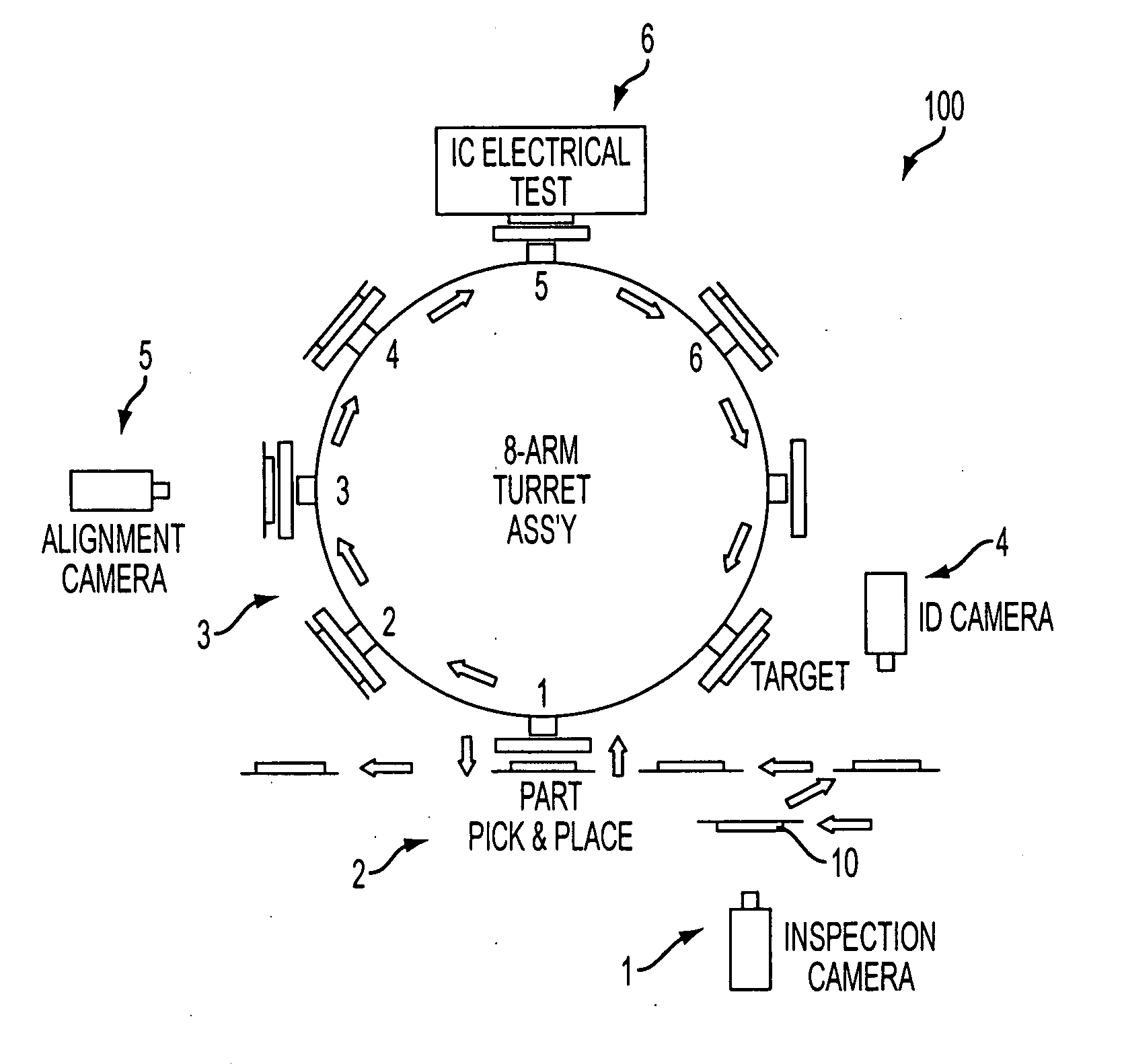
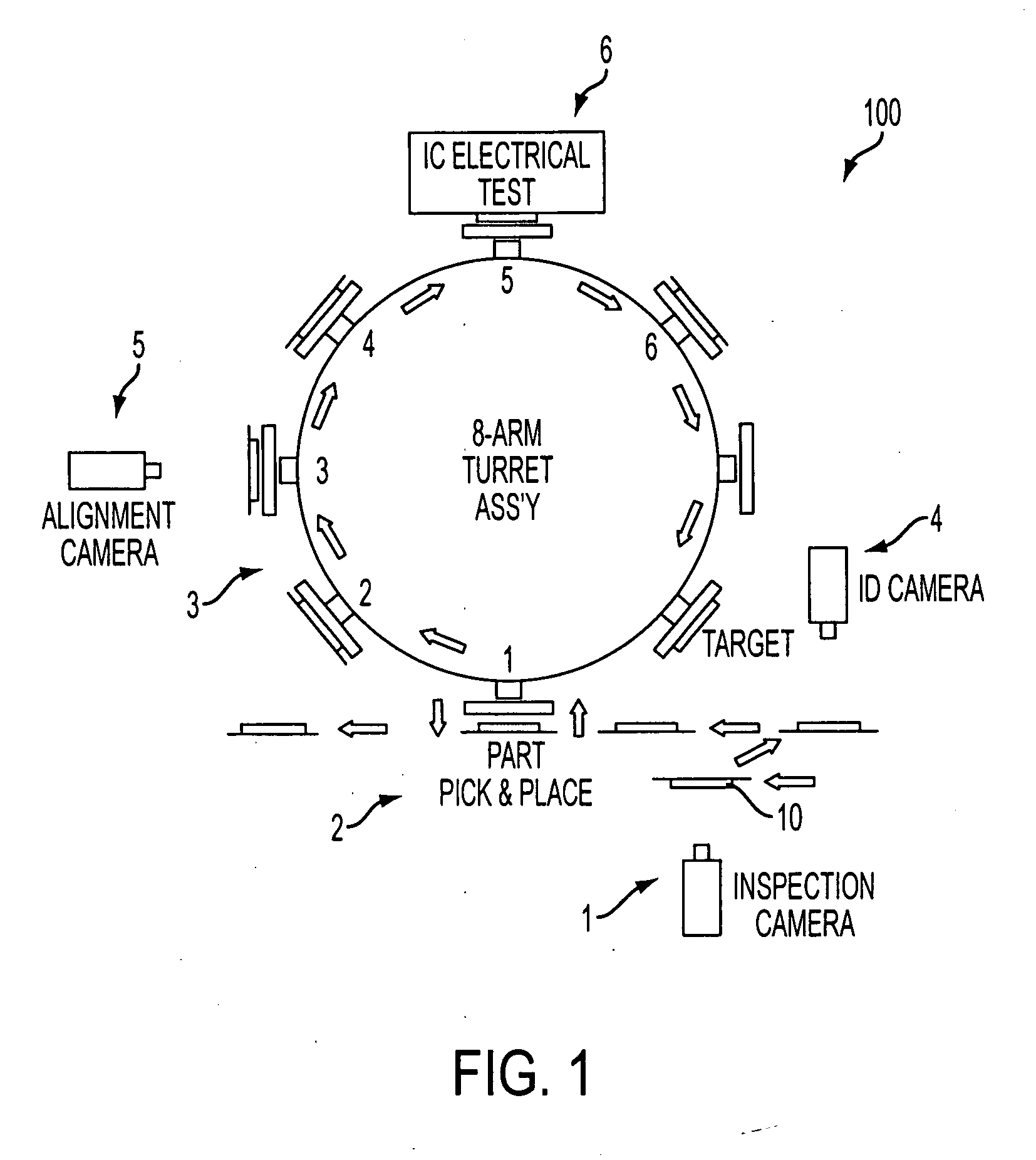
[0025] Generally, IC inspection systems carry out a number of individual tests on each IC device during and after the manufacturing process. FIG. 1 depicts the workflow of one illustrative IC inspection system 100 in which the invention may be incorporated. It will be appreciated that the invention may be used in other inspection systems. In this example, the IC device 10 is inspected at various stations throughout the IC inspection system 100. The IC device 10 is moved through the IC inspection system 100 on a carrier via a part handler. The part handler of this example may consist of a pick and place handler 2 and a multiple-arm turret assembly 3. A pick and place handler 2 and turret assembly 3 are used to move and position IC devices 10 during various manufacturing phases.

[0026] In this particular example, several inspection steps, using different systems are employed to test each IC device 10. As shown in FIG. 1, three inspection stations use vision systems. The physical defec...


PUM


Abstract

An inspection system, for inspecting pin grid arrays on integrated circuit devices includes a pin base mask configured to receive a device having a pin grid array. A dark-field, low-angle lighting system emits light onto the pin grid array. The pin base mask and low-angle lighting system provide for a clear and definitive image of the pin grid array. A camera captures the image of the pin grid array. A processor, coupled to the camera, analyzes the images captured by the camera. Based on the captured image, the processor determines whether any pins on the pin grid array are bent or missing, or whether there are extra pins present.

Description

CROSS-REFERENCE TO RELATED PATENT APPLICATIONS [0001] This application claims priority from Provisional U.S. Application No. 60 / 725,296, filed Oct. 12, 2005, incorporated herein by reference in its entirety.FIELD OF INVENTION [0002] The present invention relates generally to a device inspection system, and more particularly to a camera-implemented pin grid array (“PGA”) inspection system. BACKGROUND OF THE INVENTION [0003] Manufacturers process and test semiconductor or integrated circuit (“IC”) devices using various types of automated machinery. Before IC devices are shipped to wholesalers or consumers, they must be tested for performance and inspected for physical defects. One physical defect that is important to identify is the presence of bent pins on IC devices having a pin grid array (“PGA”). [0004] Generally, mechanical systems or basic camera systems are employed to identify bent pins. However, current mechanical and camera systems are limited in their ability to detect bent...

Claims


Application Information

Patent Timeline
IPC IPC(8): G01R31/26
CPCG01N21/95684G01N2021/8822G01R31/046G01R31/2896G01R31/70
Inventor DING, KEXIANG KEN
Owner DELTA DESIGN
Why Eureka
Try Eureka