Vehicle lamp

a technology for lamps and vehicles, applied in the field of lamps for vehicles, can solve the problems of poor welding, deformation, deformation, etc., difficult to actually eliminate post-injection molding shrinkage, deformation, etc., and achieve the effect of improving workability and rigidity

Inactive Publication Date: 2007-04-12
KOITO MFG CO LTD
View PDF16 Cites 7 Cited by
  • Summary
  • Abstract
  • Description
  • Claims
  • Application Information

AI Technical Summary

Benefits of technology

[0012] Therefore, the welding surface of the transparent cover is free of any region where rigidity extremely increases due to a shape of the welding surface. Thus, even where there is a slight gap between the welding surfaces of the housing and transparent cover in a post-mold state, the welding surface of the transparent cover can be placed into close contact with the welding surface of the housing, or the gap can be reduced to 0.1 mm or less by externally applying pressure to the transparent cover and deforming the welding surface. Consequently, heat sufficiently conducts to the welding surface of the housing during beam welding, and welding is surely performed.
[0013] According to a second aspect of one or more embodiments of the invention, the transparent cover may have a wall thickness of 4 mm or less in a region where the welding surface is formed. Therefore, when the transparent cover is pressed toward the housing by a jig or the like so as to apply an external force, the welding surface of the transparent cover easily becomes deformed and fits well to the welding surface of the housing. Namely, the welding surface of the transparent cover can be placed into close contact with the welding surface of the housing, or the gap can be reduced to 0.1 mm or less. This allows heat to sufficiently conduct to the welding surface of the housing during beam welding, and welding is surely performed.
[0014] According to a third aspect of one or more embodiments of the invention, the welding surface may slightly project with respect to the second surface adjacent thereto. This makes it possible to provide a reference line in a position between a die surface corresponding to the welding surface and other part of die surface, the reference line being used when polishing a die surface into a mirror surface in a region corresponding to the second surface of the transparent cover where the welding surface is not formed. Therefore, workability in a polishing work improves.
[0015] According to a fourth aspect of one or more embodiments of the invention, an on-housing welding surface, to which the welding surface of the transparent cover is to be welded, may be formed on the housing, and the on-housing welding surface may be formed such that the on-housing welding surface has a three-dimensional curved surface in a closed-curve form, and such that each continuing surfaces of the on-housing welding surface is formed as a flat surface with respect to a direction of a normal line thereto or as a curved surface having a curvature radius of 30 mm or more with respect to a direction of a normal line thereto. Therefore, the welding surface of the transparent cover having a shape which corresponds to the welding surface of the housing is readily placed in close contact with the welding surface of the housing. Even if there is a gap, the gap can be reduced to 0.1 mm or less.

Problems solved by technology

However, it is difficult to actually eliminate post-injection-mold shrink, deflection, deformation, etc., and it is inevitable to encounter regions having a gap of 0.1 mm or greater.
Therefore, poor welding results in such regions.
In such regions, it is not easy to place the welding surfaces of the transparent cover 70 and the housing 60 within a gap of 0.1 mm even if pushed by a jig.

Method used


Image

  • Vehicle lamp
  • Vehicle lamp
  • Vehicle lamp

Examples


Embodiment Construction

[0022] Exemplary embodiments according to the present invention will be described below with reference to the drawings.

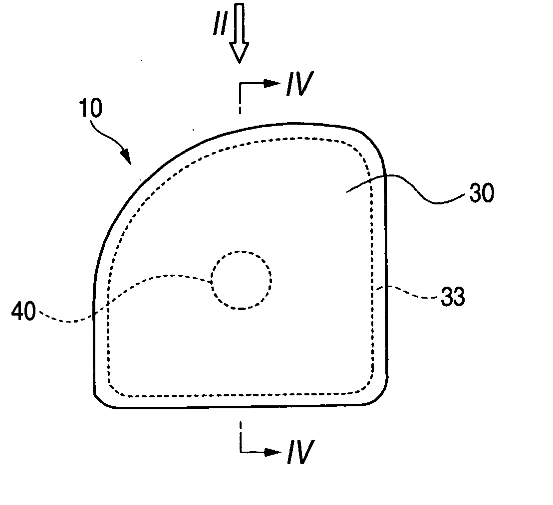
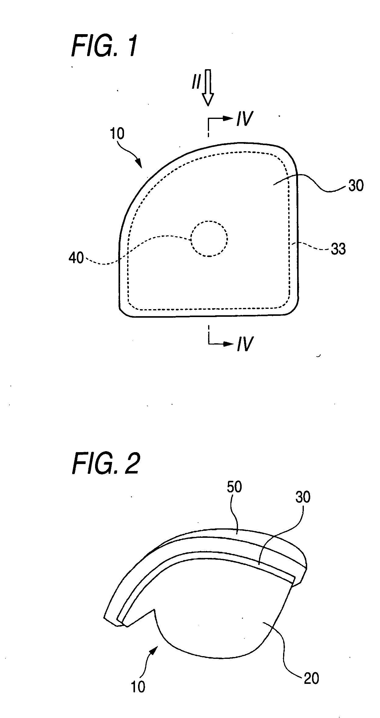
[0023] A vehicle lamp 10 is constructed such that a transparent cover 30 is joined to a vessel-like housing 20 so as to cover a front opening of housing 20, and a light-source bulb 40 is disposed in a lamp space 11 defined by the housing 20 and the transparent cover 30.

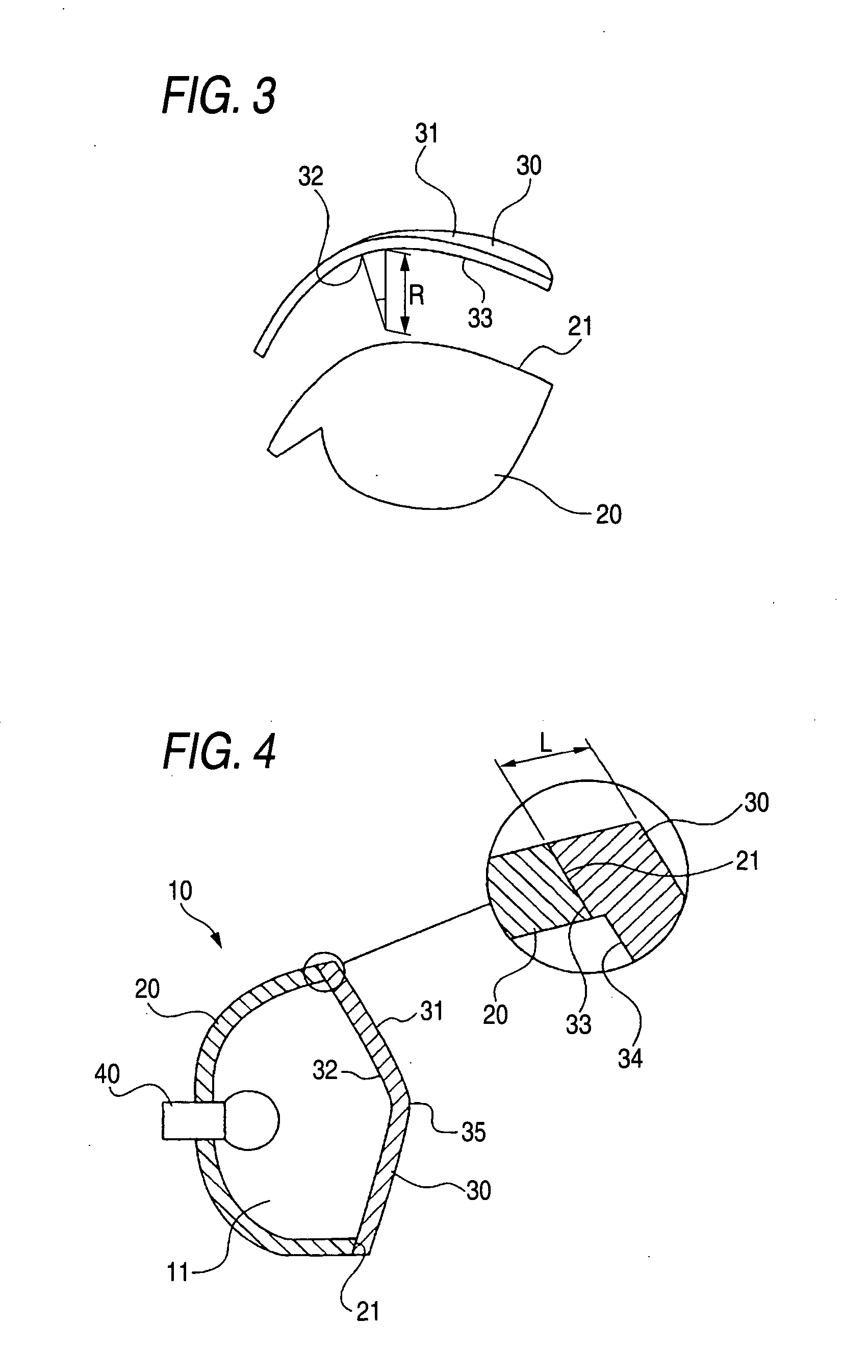
[0024] The transparent cover 30 is joined to the housing 20 by beam welding in which welding is performed by irradiation of a beam, such as a laser beam.

[0025] The transparent cover 30 is formed of a transparent resin having a flexural modulus of 2000 MPa or more, e.g. acrylic resin or polycarbonate (PC), to have a first surface 31 facing outside and a second surface 32 facing the housing 20. A welding surface 33 is formed along a circumference of the second surface 32. The welding surface is formed is formed such that the welding surface has a three-dimensional curved surface in a closed-curve for...


PUM

PropertyMeasurementUnit
flexural modulusaaaaaaaaaa
curvature radiusaaaaaaaaaa
thicknessaaaaaaaaaa

Abstract

A vehicle lamp has a housing and a transparent cover formed of a transparent resin having a flexural modulus of 2000 MPa or more, and joined to the housing by beam welding. The transparent cover has a first surface and a second surface. The second surface faces the housing, and a welding surface is formed along a circumference of the second surface. The welding surface is formed such that the welding surface has a three-dimensional curved surface in a closed-curve form, and such that each continuing surface of the welding surface is formed as a flat surface with respect to a direction of a normal line thereto or as a curved surface having a curvature radius of 30 mm or more with respect to a direction of a normal line thereto.

Description

BACKGROUND OF INVENTION [0001] 1. Field of the Invention [0002] The present invention relates generally to a vehicle lamp. Specifically, embodiments of the present invention relate to an art for surely performing welding in a vehicle lamp in which a housing and a transparent cover provided in front thereof are joined by beam welding. [0003] 2. Description of the Related Art [0004] For vehicle lamps, there exists an art of beam welding in which a transparent cover provided in front of a housing is welded onto the housing by irradiation of a beam, such as a laser beam. In joining the housing and the transparent cover by use of beam welding, there are many advantages that cannot be obtained in other joining techniques such as heat plate welding, ultrasonic welding, or bonding. [0005] Meanwhile, in order to surely perform beam welding, the housing and the transparent cover must be placed in close contact at their welding surfaces, and a gap between the welding surfaces must be held with...

Claims


Application Information

Patent Timeline
Patent Type & Authority Applications(United States)
IPC IPC(8): F21V1/00F21W107/10
CPCB29C65/1635B29C66/301B29C66/54B29L2031/3055B29L2031/747F21S48/1208B29C66/1162B29C65/168B29C65/1683B29C66/1142B29C66/542B29C66/73921B29C66/71F21S41/29B29K2033/08B29K2033/12B29K2069/00B60Q1/04B29C65/00
Inventor YAMAMOTO, AKINORI
Owner KOITO MFG CO LTD
Why Eureka
Try Eureka