
Mechanism for attaching trimmer line strips to a head of a trimming apparatus

a technology of trimming apparatus and trimmer, which is applied in the direction of metal working apparatus, agriculture tools and machines, etc., can solve the problems of strip only being about 4 to about 24 inches long, worn and abraded monofilament lines, and oftentimes breaking, so as to achieve quick and easy inserting of one end, effectively holding the trimmer line strip in place while in operation

Inactive Publication Date: 2007-04-19
SHAKESPEARE CO
View PDF11 Cites 24 Cited by
  • Summary
  • Abstract
  • Description
  • Claims
  • Application Information

AI Technical Summary

Benefits of technology

"The present invention is about a trimming apparatus with a trimmer head that uses trimmer line strips as the cutting element. The invention includes an impinging gear mechanism that allows easy insertion and holding of trimmer line strips in place during operation. The trimmer head is designed for one trimmer line strip per opening, and it has a central axis of rotation. The invention also provides a simple and durable gripping mechanism for securing the trimmer line strips. The invention allows for quick and easy re-strung of the trimmer line strips with different gauges. Overall, the invention improves the efficiency and ease of use of trimming apparatuses."

Problems solved by technology

Cutting of grass, brush and weeds eventually causes the monofilament line to become worn and abraded, and oftentimes, to break.
However, these strips are only about 4 to about 24 inches long, depending upon the size and type of trimming device employed.
Notwithstanding the diameter of the monofilament, all plastic monofilament lines, whether short strips or long wound lengths, eventually wear out or break with use.
A trimmer head that requires tools and disassembly of any portion of the head in order to change the trimmer line strip delays operation and, oftentimes, prevents the user from changing the strip or strips in the field.

Method used


Image

  • Mechanism for attaching trimmer line strips to a head of a trimming apparatus
  • Mechanism for attaching trimmer line strips to a head of a trimming apparatus
  • Mechanism for attaching trimmer line strips to a head of a trimming apparatus

Examples


Embodiment Construction

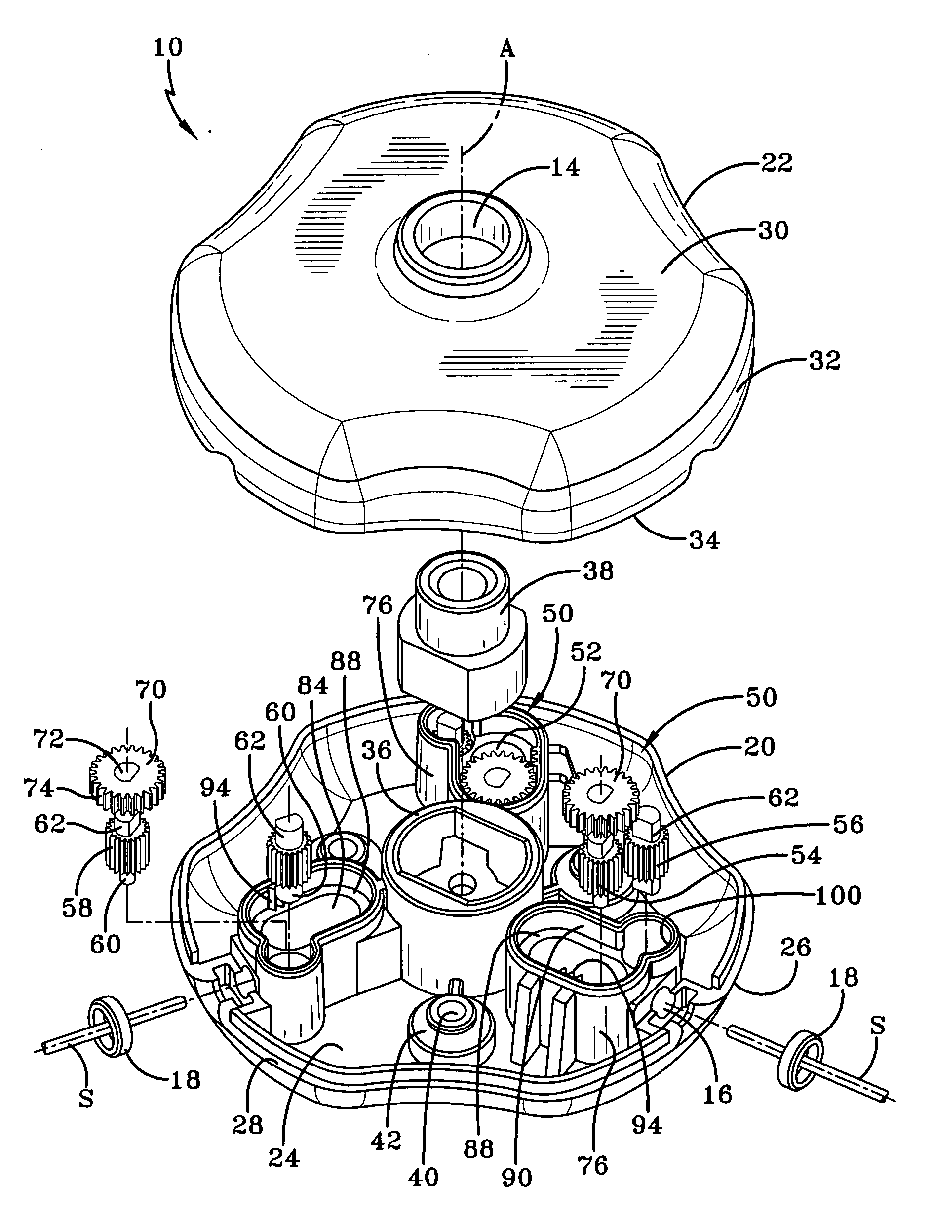
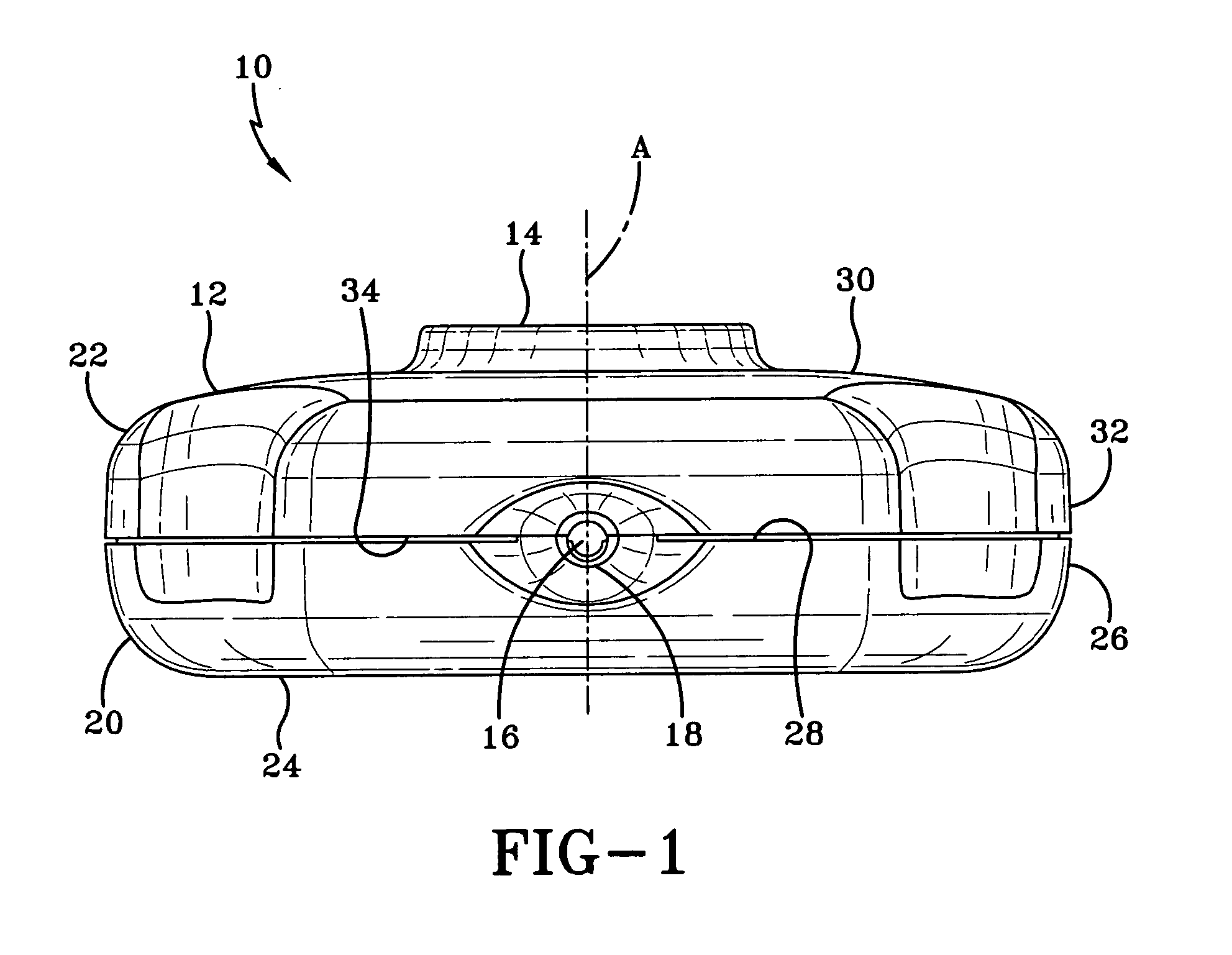
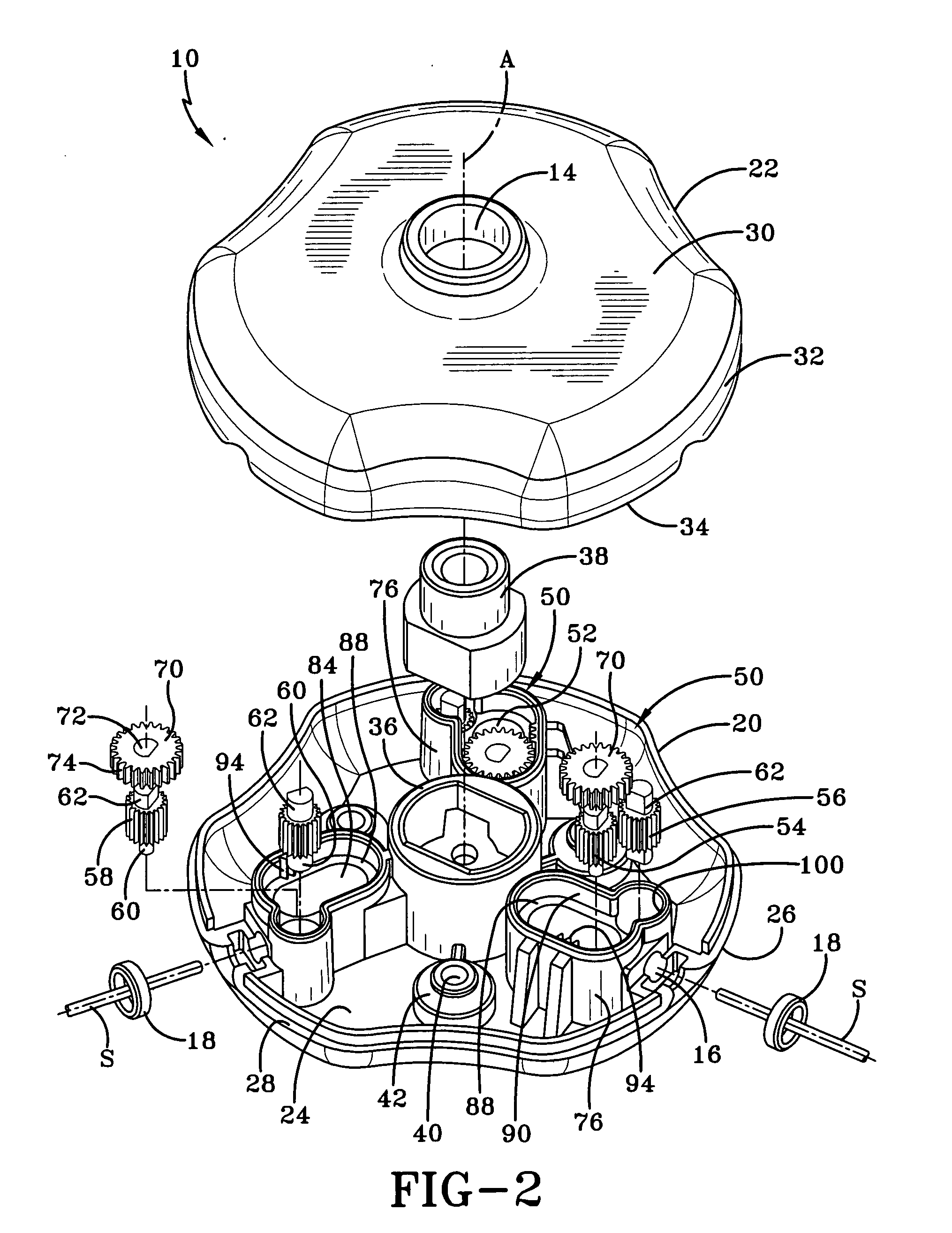
[0022] One representation of a trimmer head embodying the concepts of the present invention is generally designated by the numeral 10 in FIG. 1. It will be appreciated that the trimmer head of the present invention may take any form known in the art and should not be limited by the particular drawings and descriptions set forth herein, the present invention being defined by the scope of the claims and its equivalent structures and means falling within the scope of those claims as recited herein. To be operatively effective in cutting weeds and grasses, trimmer head 10 should be of the type capable of utilizing at least one trimmer line strip S as a cutting element. Such trimmer head may also be capable of performing other functions using other elements such as blades or brushes in replacement of the trimmer line strip S; however, the present invention is more particularly directed to the use of the trimmer head 10 with the trimmer line strip S.

[0023] The trimmer head 10 of the pres...


PUM


Abstract

A trimmer head includes a housing encasing one or more impinging gear mechanisms. Each impinging gear mechanism includes at least one guide chamber disposed in the housing of trimmer head, and a pair of gripping gears located on opposed sides of an opening through which the trimmer line strip is received. The gripping gears engage the trimmer line strip upon insertion of the strip into the housing. At least one of the pair of gripping gears is located within the guide chamber and is movable linearly with respect to guide chamber, to permit securing of the trimmer line strip between the pair of gripping gears.

Description

TECHNICAL FIELD [0001] This invention relates generally to a weed trimming apparatus and, more particularly, to a head of the weed trimming apparatus. The head of the trimming apparatus should be of the type capable of accepting flexible trimmer line strips as the cutting elements. Specifically, the present invention relates to an impinging gear mechanism adapted for securing at least one trimmer line strip within the head of the trimming apparatus. BACKGROUND OF THE INVENTION [0002] Grass, brush and weed trimming devices, utilizing a cutting element in the form of segments or strips of plastic string trimmer line, have become popular for trimming lawns and other landscapes. Most of these trimming devices, often referred to as trimmers, are electric or gas-powered, hand-held devices employing a rotatable trimmer head mounted onto a carrying handle so that the user can utilize the trimmer in a standing position. In older versions, the cutting element in these types of trimming device...

Claims


Application Information

Patent Timeline
Patent Type & Authority Applications(United States)
IPC IPC(8): B26B7/00
CPCA01D34/416
Inventor BENNETT, JAMES A.
Owner SHAKESPEARE CO
Learn More