
Snow-Blower

a technology of snowblower and shovel, which is applied in the field of snowblower, can solve the problems of laborious snow removal, low physical strength, and decreased number of young people, and achieve the effect of excellent solving

Inactive Publication Date: 2007-04-19
UMEMURA TERUYOSHI
View PDF15 Cites 8 Cited by
  • Summary
  • Abstract
  • Description
  • Claims
  • Application Information

AI Technical Summary

Benefits of technology

[0017] The small-sized snow-blower of this invention can be produced to be lightweight and compact, and the auger of the snow-blower can be lifted up above snow-banks. Therefore, using the snow-blower, even aged persons or women can easily dispose of hard accumulated snow (in particular, snow-banks) having a height of 50 cm or more. Particularly when the snow-blower is structured such that the auger is rotated in an upwardly cutting direction, advantageously, the operator can manipulate the snow-blower easily as he feels cutting forces as a resistance to hands. Thus, the snow-blower of this invention exhibits excellent effects of solving aging-society-related or nuclear-family-related problems in terms of domestic snow removal in snowy regions.

Problems solved by technology

In recent years, the number of young people has been decreasing in such regions, due to a trend toward nuclear families and aging of society, and thus, such manual snow removal, which is laborious, must be performed by aged persons or women with little physical strength.
However, as described in Non-Patent Document 1, the aforementioned snow-blower is 100 kg or more in spite of its relatively small size, and thus the snow-blower cannot be easily handled by aged persons or women.
In addition, difficulty is encountered in commercially providing such a snow-blower at low price, in view of its structure, and improvement is awaited for simplified operation or noise reduction.
However, when this snow-blower is employed for cutting hard snow-banks, there is a problem that the snow-blower per se mounts on the snow-banks, and the cutting speed of the auger cannot be increased.
Moreover, since this snow-blower does not have a mechanism for moving the auger up and down, when the snow-blower is employed for disposing of high snow-banks, the entirety of the snow-blower must be lifted up by the operator, and then mounted on the snow-banks.
Thus, the height of snow-banks which can be disposed of with this snow-blower by a typical operator is limited to about 25 cm or less.
Meanwhile, no particular measures have been taken for reducing engine noise in this proposed snow-blower, and therefore the snow-blower has not yet acquired popularity, despite having been commercialized as a practical product.
However, since this snow-blower does not have a mechanism for moving an auger up and down, the height of snow-banks which can be disposed of with this snow-blower is limited to about 25 cm or less.
In addition, a light weight blade employed in this snow-blower cannot cut hard snow-banks.
However, this proposed snow-blower does not have a mechanism for moving an auger up and down, and thus issues a problem in that the height of snow-banks which can be disposed of with the snow-blower is limited to about 25 cm or less.

Method used


Image

  • Snow-Blower
  • Snow-Blower
  • Snow-Blower

Examples


example 1

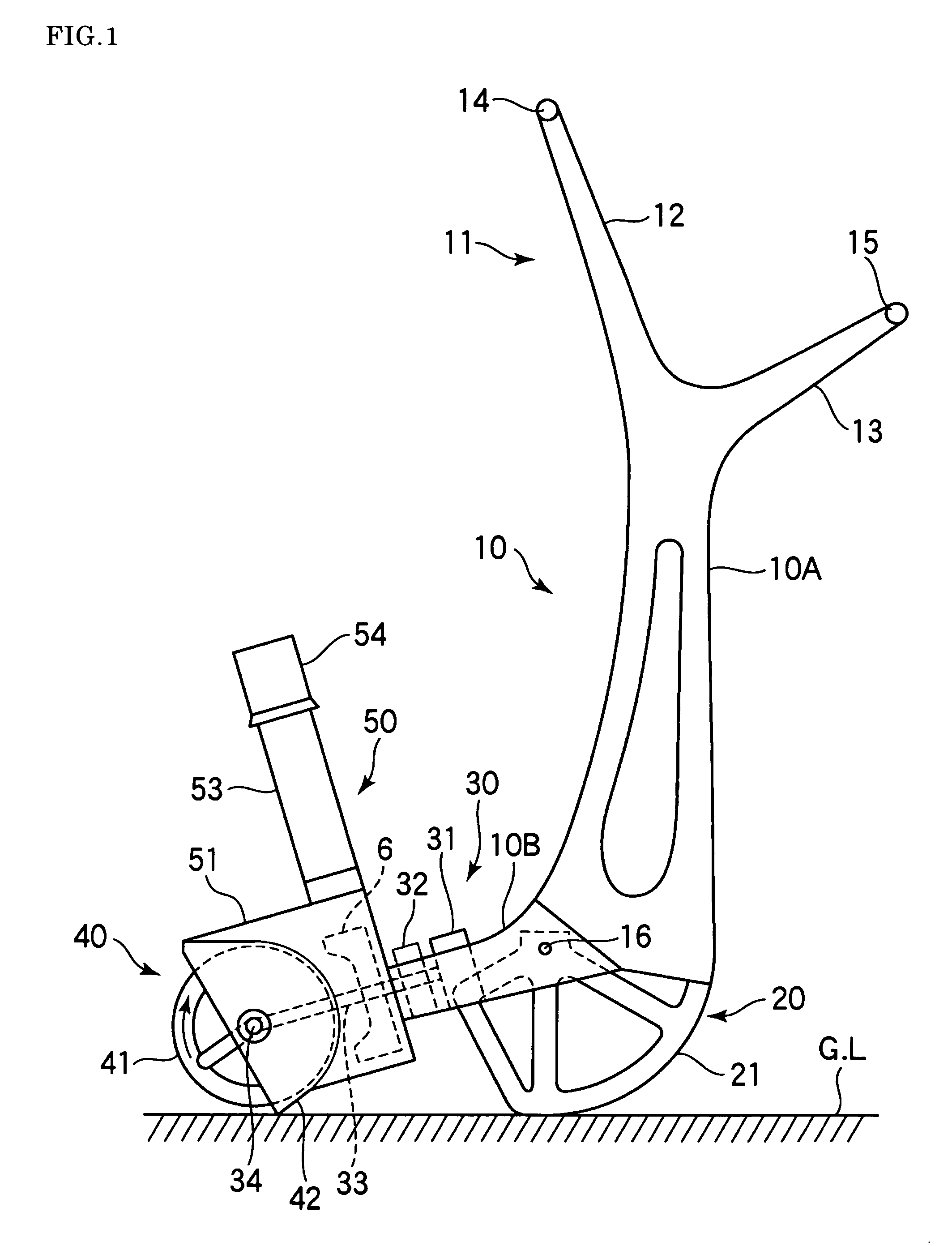
[0038] A snow-blower according to the first embodiment was employed, where the fulcrum 16 of a frame 10 was positioned 213 mm above ground level, and arc-shaped sliders 21 having a radius of 213 mm (as measured from the fulcrum serving as the center of the sliders) were provided such that the frame 10 was swiveled about the fulcrum 16. An auger having a diameter of 220 mm was provided at a position 410 mm in front of the fulcrum 16, and a lower handlebar 15 was provided at a position 1,000 mm backward of the fulcrum 16. The angle of the lower handlebar 15 as viewed from the fulcrum 16 was set at 60° from the horizontal level. With this structure, when the auger is positioned on the ground, the level of the lower handlebar 1 is 1,079 mm, which is almost equal to human shoulder level. Subsequently, when the lower handlebar 15 is moved downward, and the frame 10 is swiveled by 60°, the lower handlebar 15 is positioned about 213 mm above ground level. At this time, an upper handlebar 14...

example 2

[0042] A snow-blower of the second embodiment was employed, where the diameter of a main auger was regulated to 140 mm; the diameter of a snow-collecting auger is regulated to 220 mm; the distance between the shaft of the main auger and that of the snow-collecting auger was regulated to 130 mm; the main auger and the snow-collecting auger were formed of spiral blades which are rotated in opposite directions; and a predetermined angle was provided between these augers such that the augers do not come into contact with each other. The snow-blower efficiently handled snow-banks having a height of about 10 cm. Values in parentheses of Table 1 correspond to the results obtained in the case of the snow-blower of Example 2. Conditions described in Table 1 other than the values shown in the parentheses are the same as those in the case of the snow-blower of Example 1. In the case of Example 2, the power source is the same as that employed in Example 1, but the weight of the snow-blower is i...


PUM


Abstract

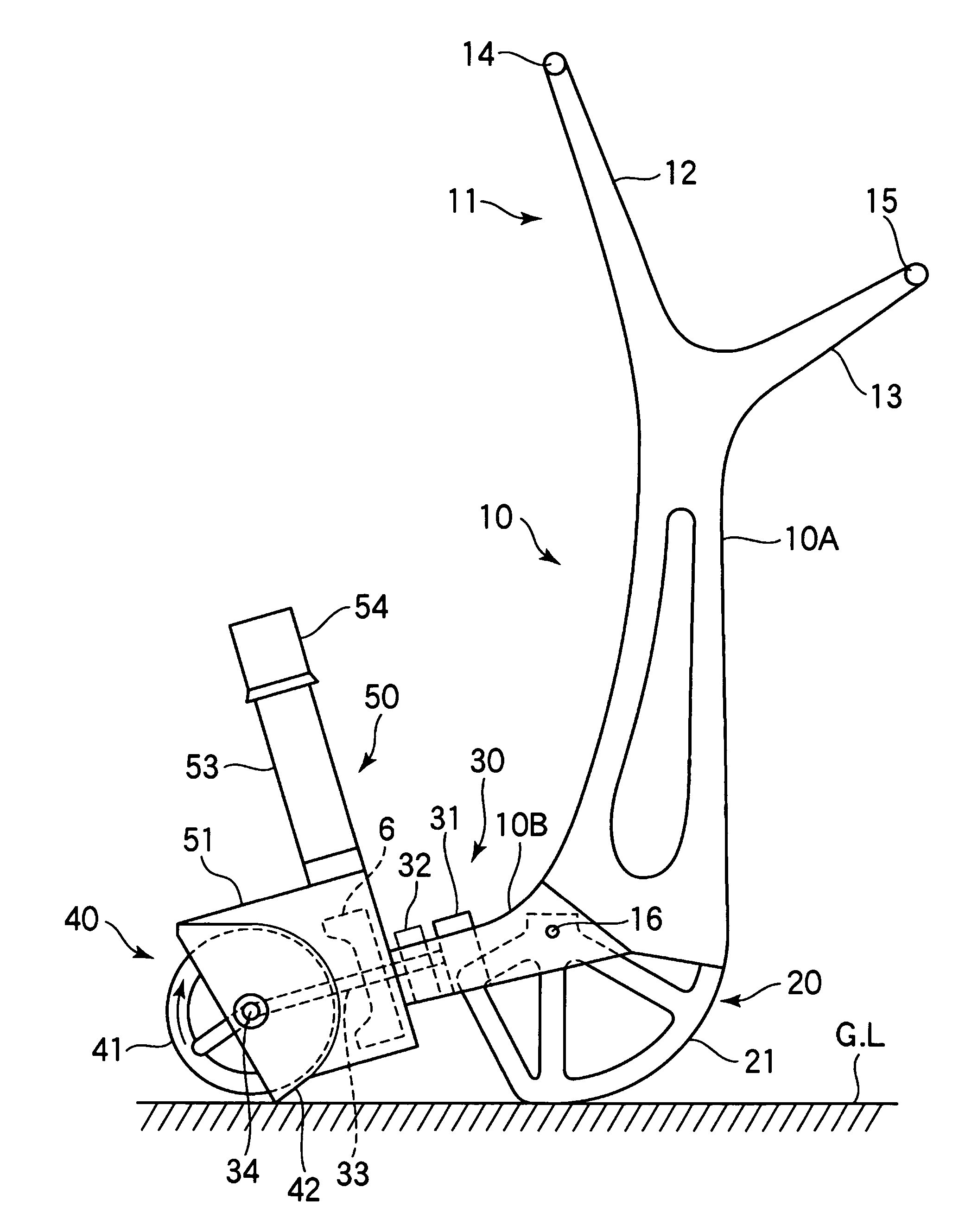
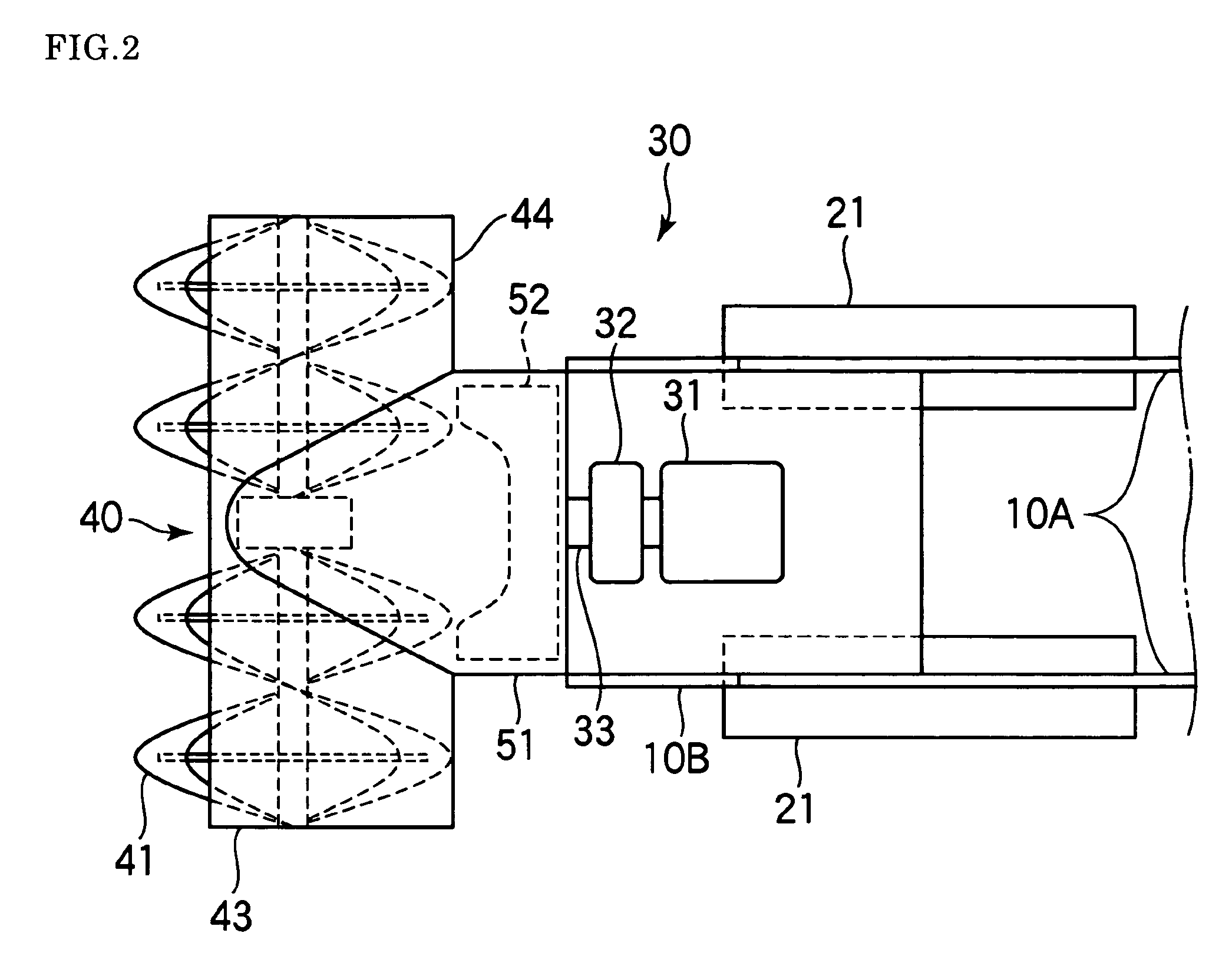
A lightweight snow-blower which can dispose of hard snow-banks having a size of more than 50 cm, and which is easy to handle by aged persons and women. The snow-blower includes a frame (10); an auger (41) for cutting accumulated snow in an upwardly cutting direction, the auger being provided on the front end side of the frame; operation handles (11, 12) provided on the rear end side of the frame; and on-snow moving means (40) which is mounted on a middle portion of the frame and includes an arc-shaped sliding member or a wheel, wherein the frame is structured such that it acts as a lever in which the portion on which the on-snow moving means (40) is mounted serves as a fulcrum (16), and such that the auger (41) can be moved up and down and back and forth by means of the operation handles (11, 12); and that the frame (10) is provided with driving means (30) for driving the auger (41). In the snow-blower, preferably, the handles (11, 12) provided on the frame (10) include upper and lower handle sections. In the snow-blower of this invention, preferably, a snow-throwing device (50) is fixed on an auger cover, and provided on a tilt-adjusting stand which can be tilted with respect to the frame by means of a link mechanism.

Description

TECHNICAL FIELD [0001] This invention relates to a snow-blower, and more particularly to a small-sized, lightweight snow-blower which is manually operated. BACKGROUND ART [0002] In snowy regions, road snow removal operations are popularized; i.e., snow accumulated on roads is removed to the asides of the roads by means of a large-sized snow removal vehicle. During such snow removal, the snow removed to a roadside is compressed and hardened, and in some cases, the removed snow forms mound-like snow-banks having a height of more than 50 cm. The thus-formed snow-banks may block paths in front of stores or houses of residents living in the snowy regions. Therefore, the residents are forced to manually remove such snow-banks with a snow scoop or a Snow Dump (which is a type of snow scoop operated by both hands) for securing the walkways for their businesses and daily life. In recent years, the number of young people has been decreasing in such regions, due to a trend toward nuclear famil...

Claims


Application Information

Patent Timeline
Patent Type & Authority Applications(United States)
IPC IPC(8): E01H5/09E01H5/04
CPCE01H5/04
Inventor UMEMURA, TERUYOSHI
Owner UMEMURA TERUYOSHI
Learn More