Performance of a combustion chamber by multiple wall perforations

a technology of perforation and combustion chamber, which is applied in the direction of combustion process, hot gas positive displacement engine plant, lighting and heating apparatus, etc., can solve the problems of increasing manufacturing time, high cost of implementation, and attendant risk of crack formation, and achieve the effect of reducing such drawbacks

Active Publication Date: 2007-04-19
SN DETUDE & DE CONSTR DE MOTEURS DAVIATION S N E C M A
View PDF21 Cites 45 Cited by
  • Summary
  • Abstract
  • Description
  • Claims
  • Application Information

AI Technical Summary

Benefits of technology

[0008] A main aim of the present invention is thus to mitigate such drawbacks by proposing an annular wall for a combustion chamber, the wall having additional bores for cooling the zones that are situated directly downstream from a primary hole or a and dilution hole.

Problems solved by technology

In practice, it has been found that those zones of the inner and outer walls that are situated directly downstream from a primary hole or a dilution hole suffer from a level of cooling that is small, with the attendant risk of cracks forming.
Given that that constitutes localized treatment, such a proposal is particularly expensive to implement and increases manufacturing time.

Method used


Image

  • Performance of a combustion chamber by multiple wall perforations
  • Performance of a combustion chamber by multiple wall perforations
  • Performance of a combustion chamber by multiple wall perforations

Examples


Embodiment Construction

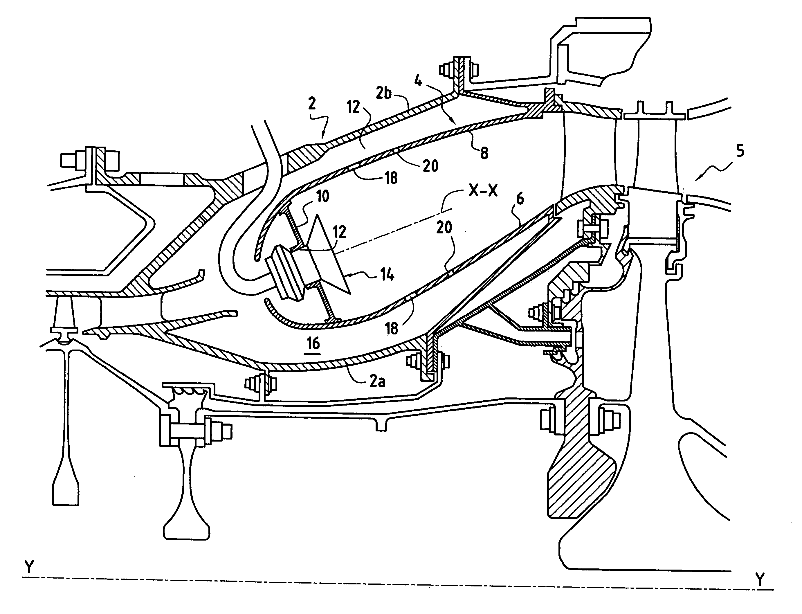
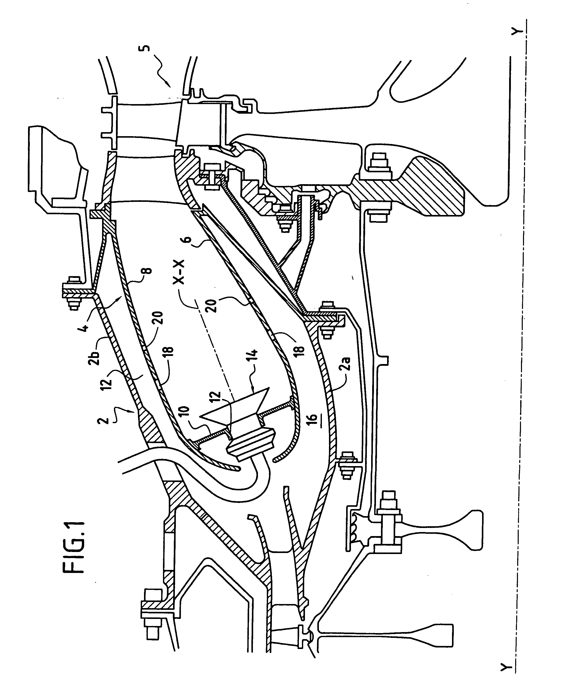
[0019]FIG. 1 shows a combustion chamber for a turbomachine. Such a turbomachine comprises in particular: a compression section (not shown) in which air is compressed prior to being injected into a chamber casing 2, and then into a combustion chamber 4 mounted inside the casing.

[0020] The compressed air is introduced into the combustion chamber and is mixed with fuel prior to being burnt therein. The gas that results from this combustion is then directed towards a high pressure turbine 5 disposed at the outlet from the combustion chamber 4.

[0021] The combustion chamber 4 is of the annular type. It is formed by an inner annular wall 6 and by an outer annular wall 8 that are united at their upstream ends by a transverse wall 10 forming an end wall of the chamber.

[0022] The inner and outer walls 6 and 8 extend along a longitudinal axis X-X that slopes slightly relative to the longitudinal axis Y-Y of the turbomachine. The chamber end 10 is provided with a plurality of openings 12 hav...


PUM


Abstract

An annular wall for the combustion chamber of a turbomachine has a cold side and a hot side, said wall being provided with a plurality of primary holes and a plurality of dilution holes distributed in circumferential rows, together with a plurality of cooling orifices that are distributed in a plurality of circumferential rows that are spaced apart axially from one another, the number of cooling orifices being identical in each row thereof, and the wall further including bores disposed immediately downstream from the primary holes and from the dilution holes and distributed in circumferential rows, the bores in any one row presenting a substantially identical diameter, being spaced apart at a pitch that is constant, and presenting intrinsic characteristics that are different from the intrinsic characteristics of the cooling orifices of the adjacent rows.

Description

[0001] The present invention relates to the general field of combustion chambers for turbomachines. It relates more particularly to an annular wall for a combustion chamber cooled by a “multiple perforation” technique. BACKGROUND OF THE INVENTION [0002] Typically, an annular combustion chamber for a turbomachine is formed by an inner annular wall and an outer annular wall that are interconnected at an upstream end by a transverse wall forming a chamber end wall. [0003] The inner and outer walls are each provided with a plurality of holes and various orifices allowing the air flowing around the combustion chamber to penetrate into it. [0004] Thus, so-called “primary” holes and “dilution” holes are formed through these walls to bring air into the inside of the combustion chamber. The air passing through the primary holes contributes to creating an air / fuel mixture which is burnt in the chamber, while the air passing through the dilution holes serves to encourage dilution of the same a...

Claims


Application Information

Patent Timeline
Patent Type & Authority Applications(United States)
IPC IPC(8): F23R3/50
CPCF23R3/002F23R3/06F23R2900/03041F23R2900/03042
Inventor BERNIER, DANIEL FRANCIS PAULCAMPION, JEAN-MICHEL JACQUESTOUCHAUD, STEPHANE HENRI GUY
Owner SN DETUDE & DE CONSTR DE MOTEURS DAVIATION S N E C M A
Why Eureka
Try Eureka