
Lighting controller for lighting device for vehicle

a technology for lighting devices and controllers, which is applied in the direction of electric lighting sources, electroluminescent light sources, transportation and packaging, etc., can solve the problems of hardly detected abnormality of multi-chip leds and hardly accurately detected led abnormalities, so as to prevent wrong decisions and high accuracy detection

Inactive Publication Date: 2007-04-19
KOITO MFG CO LTD
View PDF6 Cites 45 Cited by
  • Summary
  • Abstract
  • Description
  • Claims
  • Application Information

AI Technical Summary

Benefits of technology

[0024] The detected value obtained when the first setting time elapses after the semiconductor light source is initially turned on is stored as the initial value. The presence or absence of the abnormality is decided when the second setting time elapses after the semiconductor light source is turned on. Accordingly, the first setting time and the second setting time are set to meet a time when the semiconductor light source is in a stable state in view of temperature after the semiconductor light source is turned on. Thus, a detecting accuracy can be prevented from being deteriorated due to the change of the temperature of the semiconductor light source.
[0040] According to one or more embodiments, a wrong decision can be prevented.

Problems solved by technology

In the method for simply comparing the previously stored forward voltage Vf with the detected forward voltage Vf, when a failure due to the change of the ambient temperature (an environment) is considered, if the forward voltage Vf is suddenly lowered or gradually lowered, the abnormality of the LED is hardly accurately detected.
Thus, the abnormality of the multi-chip LED is hardly detected.

Method used


Image

  • Lighting controller for lighting device for vehicle
  • Lighting controller for lighting device for vehicle
  • Lighting controller for lighting device for vehicle

Examples


Embodiment Construction

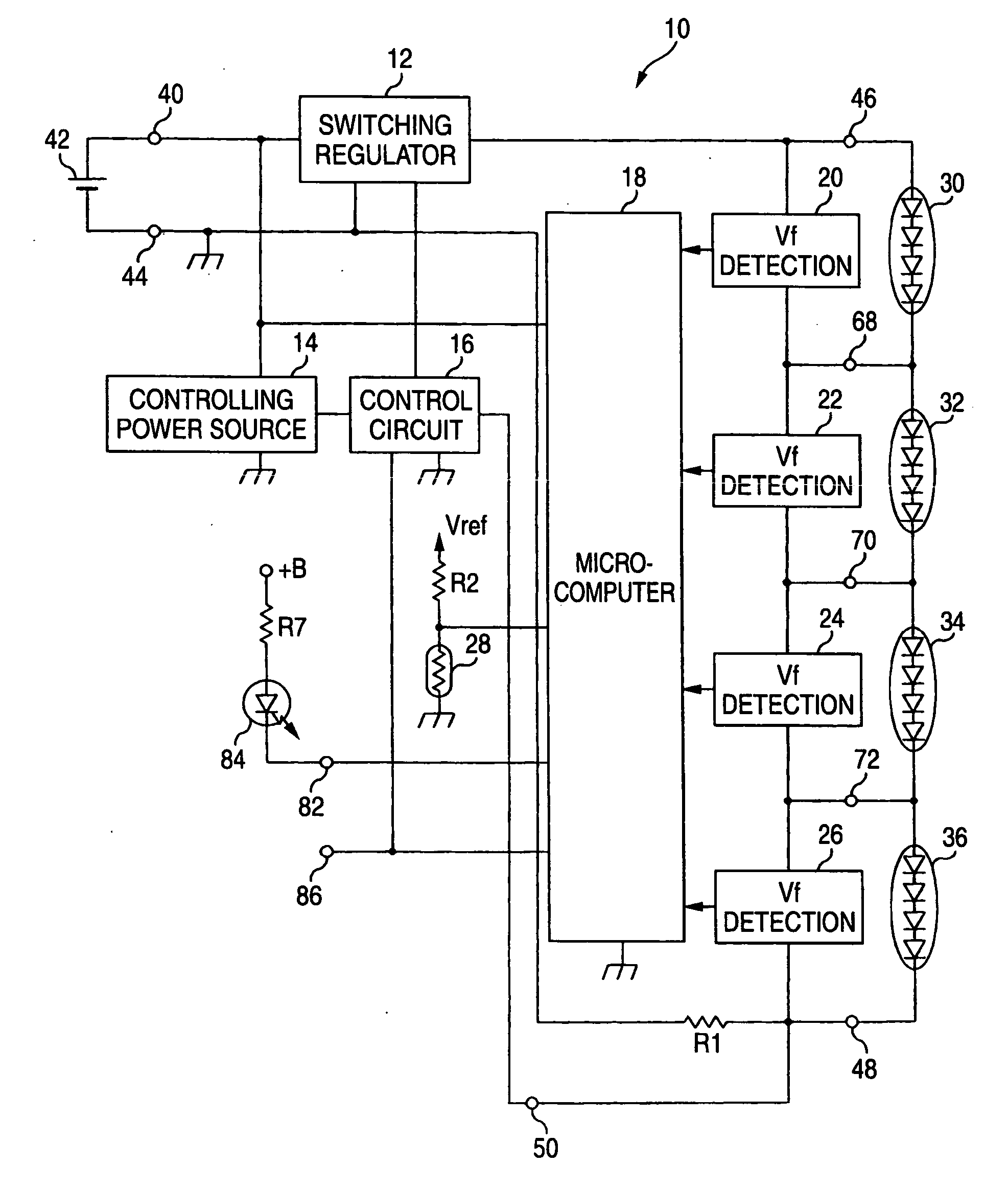
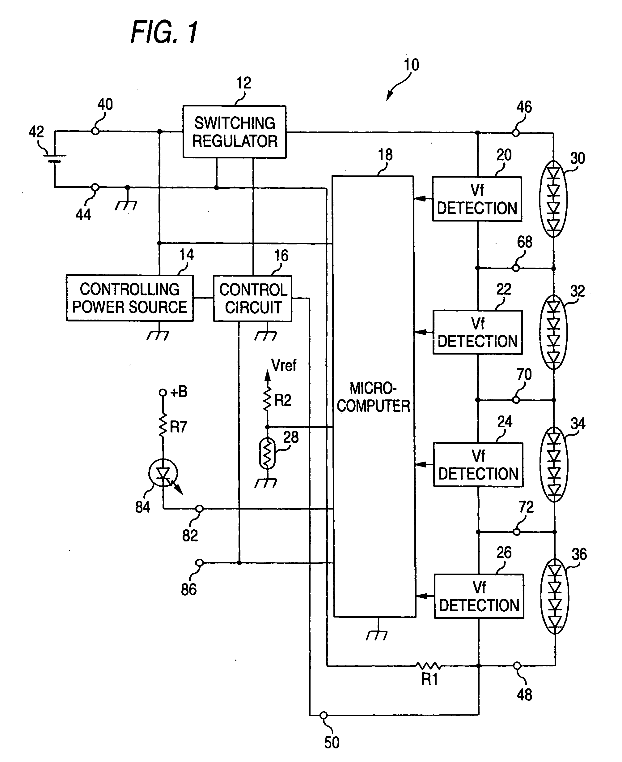
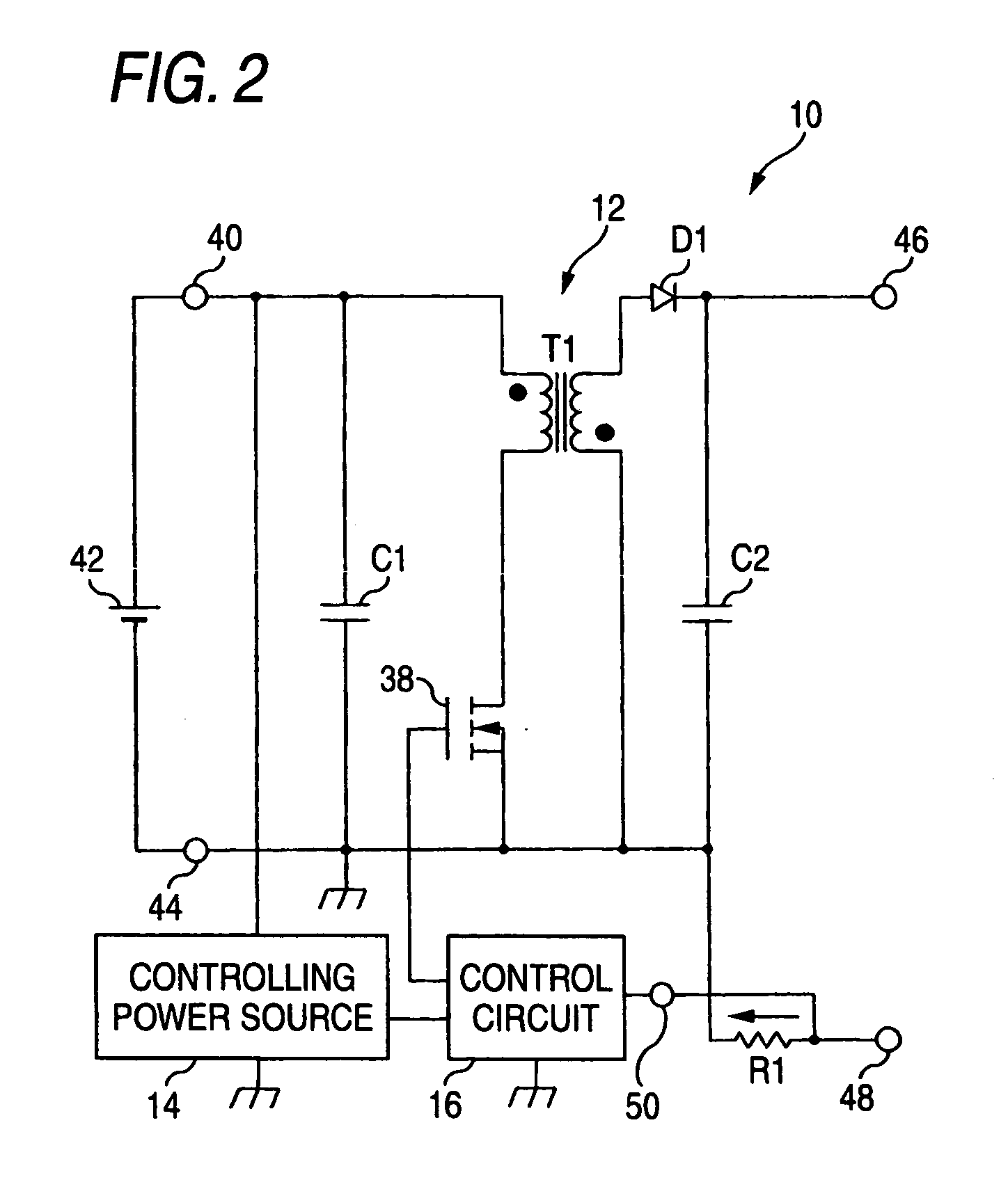
[0053] Now, embodiments of the present invention will be described below. FIG. 1 is a circuit block diagram of a lighting controller for a lighting device for a vehicle showing one embodiment of the present invention. FIG. 2 is a block diagram for a circuit of a controlling power source.

[0054]FIG. 3 is a circuit block diagram showing a switching regulator. FIG. 4 is a circuit block diagram of a control circuit. FIG. 5 is a wave form diagram for explaining the operation of the control circuit. FIG. 6 is a circuit block diagram showing one example of a forward voltage detecting circuit. FIG. 7 is a circuit block diagram showing one example of the forward voltage detecting circuit. FIG. 8 is a characteristic view showing Vf-If characteristics of an LED. FIG. 9 is a flowchart for explaining the operation of the lighting controller for a lighting device for a vehicle shown in FIG. 1. FIG. 10 is a circuit block diagram of a lighting controller for a lighting device for a vehicle showing ...


PUM


Abstract

In a process in which a current is supplied from a switching regulator to multi-chip LEDs, the forward voltages of the LEDs are respectively detected in forward detecting circuits. The detected values are sent to a microcomputer. In the microcomputer, detected values when the multi-chip LEDs are initially turned on are stored as initial values. A first abnormality deciding value is set from the initial value. The detected values are sequentially stored as updated values. Second abnormality deciding values having conditions stricter than those of the first abnormality deciding value are sequentially set in accordance with the stored updated value. A read value is compared with the first abnormality deciding value or the read value is compared with the second abnormality deciding value to decide whether or not the abnormality of the LEDs is present. When it is decided that the LEDs are abnormal, an LED is turned on to inform a driver of the presence of the abnormality.

Description

BACKGROUND OF INVENTION [0001] 1. Field of the Invention [0002] The present invention relates to a lighting controller for a lighting device for a vehicle, and more particularly to a lighting controller for a lighting device for a vehicle constructed so as to control the lighting operation of a semiconductor light source. [0003] 2. Background Art [0004] As a lighting device for a vehicle, lighting devices using semiconductor light emitting element such as an LED (Light Emitting Diode) as a light source have been known. On such a lighting device for a vehicle, a lighting control circuit for controlling the lighting operation of the LED is mounted. [0005] As the lighting control circuit, for example, a lighting control circuit has been proposed in which the battery voltage of the vehicle is boosted and the boosted voltage is applied to LEDs to drive the light source having a plurality of the LEDs connected in series (see Patent Document 1). [0006] As the LED of the lighting device for...

Claims


Application Information

Patent Timeline
Patent Type & Authority Applications(United States)
IPC IPC(8): H05B37/00B60Q11/00H01L33/00H05B44/00
CPCH05B33/0815H05B33/083H05B33/0851H05B33/0854H05B33/0893H05B45/58H05B45/48H05B45/18H05B45/3725
Inventor TAKEDA, HITOSHINAKAYAMA, TORUITO, MASAYASU
Owner KOITO MFG CO LTD
Learn More