RF front-end architecture for a separate non-50 ohm antenna system

a technology of rf front-end and antenna system, which is applied in the direction of antennas, antenna details, electrical equipment, etc., can solve the problems of reducing the performance of antennas, difficulty in designing signal antennas for both 1 ghz band and 2 ghz bands, and inability to match for each band in such splitting

Inactive Publication Date: 2007-04-19
NOKIA CORP
View PDF11 Cites 57 Cited by
  • Summary
  • Abstract
  • Description
  • Claims
  • Application Information

AI Technical Summary

Problems solved by technology

A major problem to be solved is how to improve the total efficiency of the antenna and the associated front-end in a mobile phone considering the variations in the user's head and hand position.
Another major problem to be solved is how to minimize the degradation in antenna performance when the ante...

Method used


Image

  • RF front-end architecture for a separate non-50 ohm antenna system
  • RF front-end architecture for a separate non-50 ohm antenna system
  • RF front-end architecture for a separate non-50 ohm antenna system

Examples


Embodiment Construction

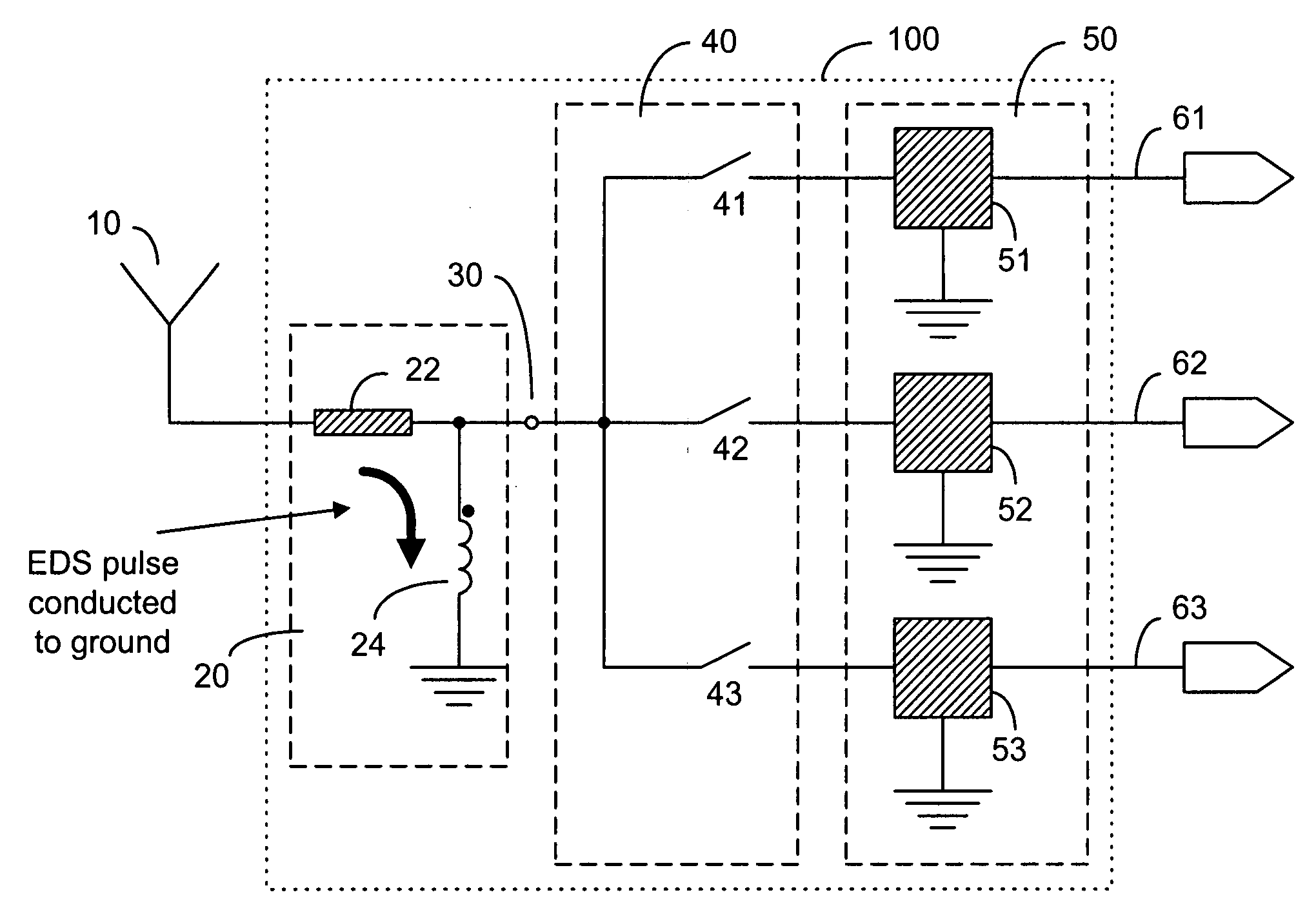
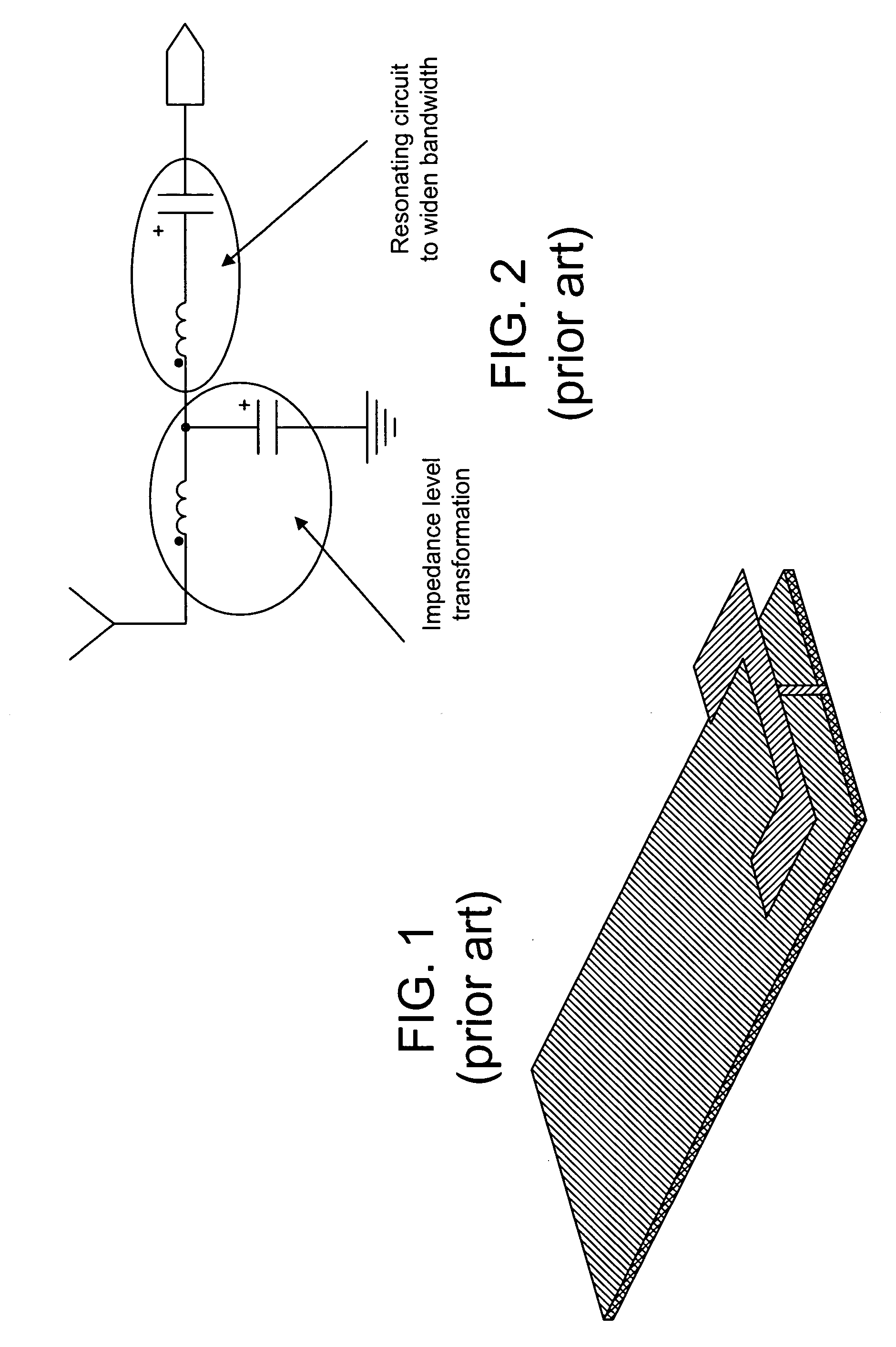
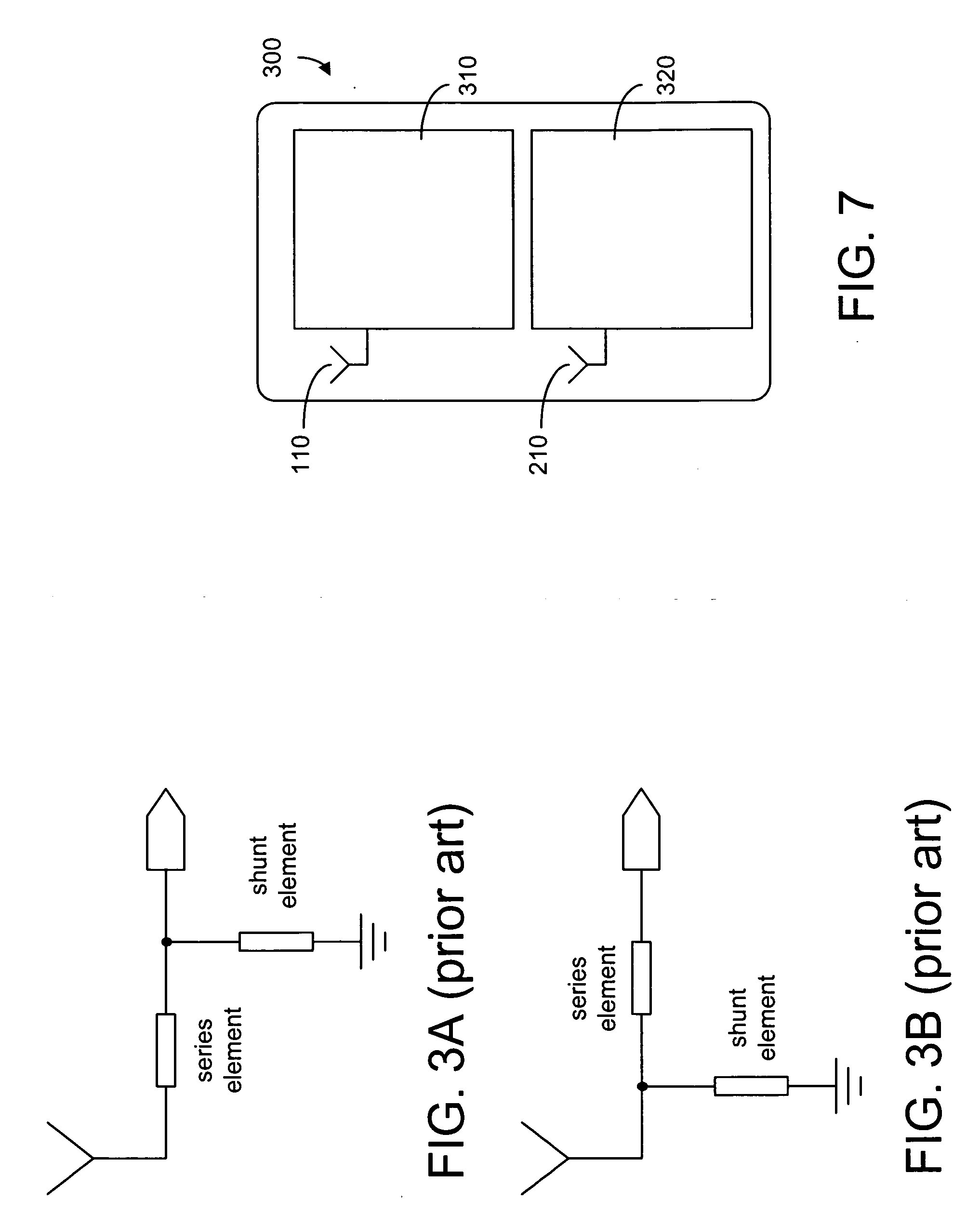
[0018] A general RF front-end architecture, according to the present invention, is shown in FIG. 4a. As shown, the RF front-end module 100 is connected to a non-50 ohm antenna 10. It is possible that the antenna 10 is also non-resonating. The RF front-end 100 comprises a switching module 40 and a matching module 50 to split the feed point to the antenna into a plurality of signal paths 61, 62, 63. As shown in FIG. 4a, the switching module 40 has a plurality of switching elements 41, 42, 43 for selecting the signal paths 61, 62, 63. Some of the signal paths 61, 62, 63 can be transmission paths and the others are reception paths. The matching module 50 has a plurality of matching networks 51, 52, 53 for separately and independently matching the antenna for the corresponding signal paths. Each of the matching networks can be as simple as those shown in FIGS. 3a and 3b. However, it is also desirable to include a resonating circuit to widen the bandwidth associated with each signal path....


PUM


Abstract

A transceiver system having an RF front-end operatively connected to two separate non-50 ohm antennas for separately providing transmission/reception paths for 1 GHz band and for 2 GHz band. A switching module is operatively connected to each antenna for mode and frequency-range selection within each band. Each switching module has a plurality of switching elements connected to a plurality of signal paths. Matching is separately and independently provided for each signal path. The matching can be achieved by using distributed elements or lumped elements arranged in shunt or series in order to widen the bandwidth. An electrostatic discharge protection circuit is provided between the antenna feed point and the switching module. The protective circuit can also be used as a discrete matching network that can be optimized depending on the phone mechanics and dimensions.

Description

FIELD OF THE INVENTION [0001] The present invention relates generally to the RF front-end part of a radio and, more particularly, to an RF front-end in a multiband, multimode communication engine in a mobile phone. BACKGROUND OF THE INVENTION [0002] It is known in the art that the conventional antenna that provides a 50 ohm interface to the front end is sensitive to disturbances in the near field (head, fingers etc). This sensitivity can be dramatically decreased if the antenna is simplified and some of the matching components are moved to the front-end. Typically antenna matching is achieved by internal parasitic loads or the like, and the matching components can be either discrete or integrated passive components. A major problem to be solved is how to improve the total efficiency of the antenna and the associated front-end in a mobile phone considering the variations in the user's head and hand position. Another major problem to be solved is how to minimize the degradation in ant...

Claims


Application Information

Patent Timeline
IPC IPC(8): H01Q1/50
CPCH01Q23/00H03H7/38H04B1/0458H04B1/18
Inventor ELLA, JUHAOLLIKAINEN, JANIRANTA, TEROZHAO, ANPINGRAHOLA, JUSSI
Owner NOKIA CORP
Why Eureka
Try Eureka