Imaging apparatus having output circuits selectably operative dependant upon usage and a method therefor

a pickup apparatus and output circuit technology, applied in the field of image pickup apparatus, can solve the problems of power saving and signal correction, inferior in signal charge reading,

Inactive Publication Date: 2007-04-19
FUJIFILM CORP
View PDF3 Cites 15 Cited by
  • Summary
  • Abstract
  • Description
  • Claims
  • Application Information

AI Technical Summary

Benefits of technology

[0011] The imaging processing method of the present invention, acquires a set condition, determines whether the condition includes a first speed mode or a second speed mode faster than the first speed mode, produces a control signal depending on the determination result, sets generation of a timing signal to provide an image signal in multiple outputs according to the determination result including the second speed mode, sets at least noise reduction and digitization on the supplied image signal on a plurality of output channels, rearranges the supplied image signal on t...

Problems solved by technology

To do so, however, power saving and signal corrections by means of a variety of processings are required due to the divided photosensitive array.
The image sensor taught by the above-identified '626 publicati...

Method used


Image

  • Imaging apparatus having output circuits selectably operative dependant upon usage and a method therefor
  • Imaging apparatus having output circuits selectably operative dependant upon usage and a method therefor
  • Imaging apparatus having output circuits selectably operative dependant upon usage and a method therefor

Examples


Embodiment Construction

[0043] With reference to the accompanying drawings, preferred embodiments of the image pickup apparatus of the present invention will be described in more detail. The instant embodiment is directed to an image pickup apparatus applied to a digital camera 10, FIG. 1. Illustration and description of portions not directly relevant to understanding the present invention will be omitted.

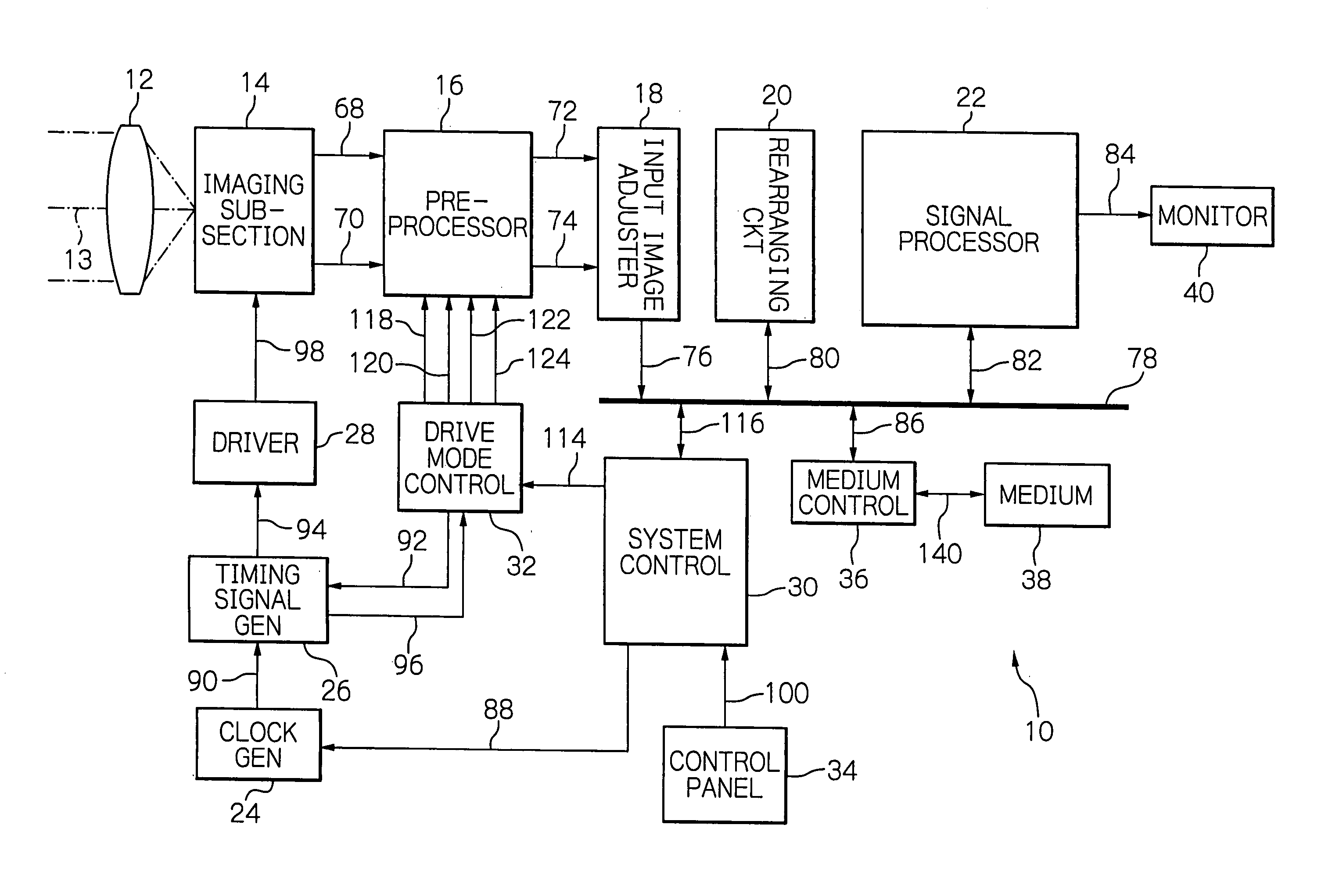
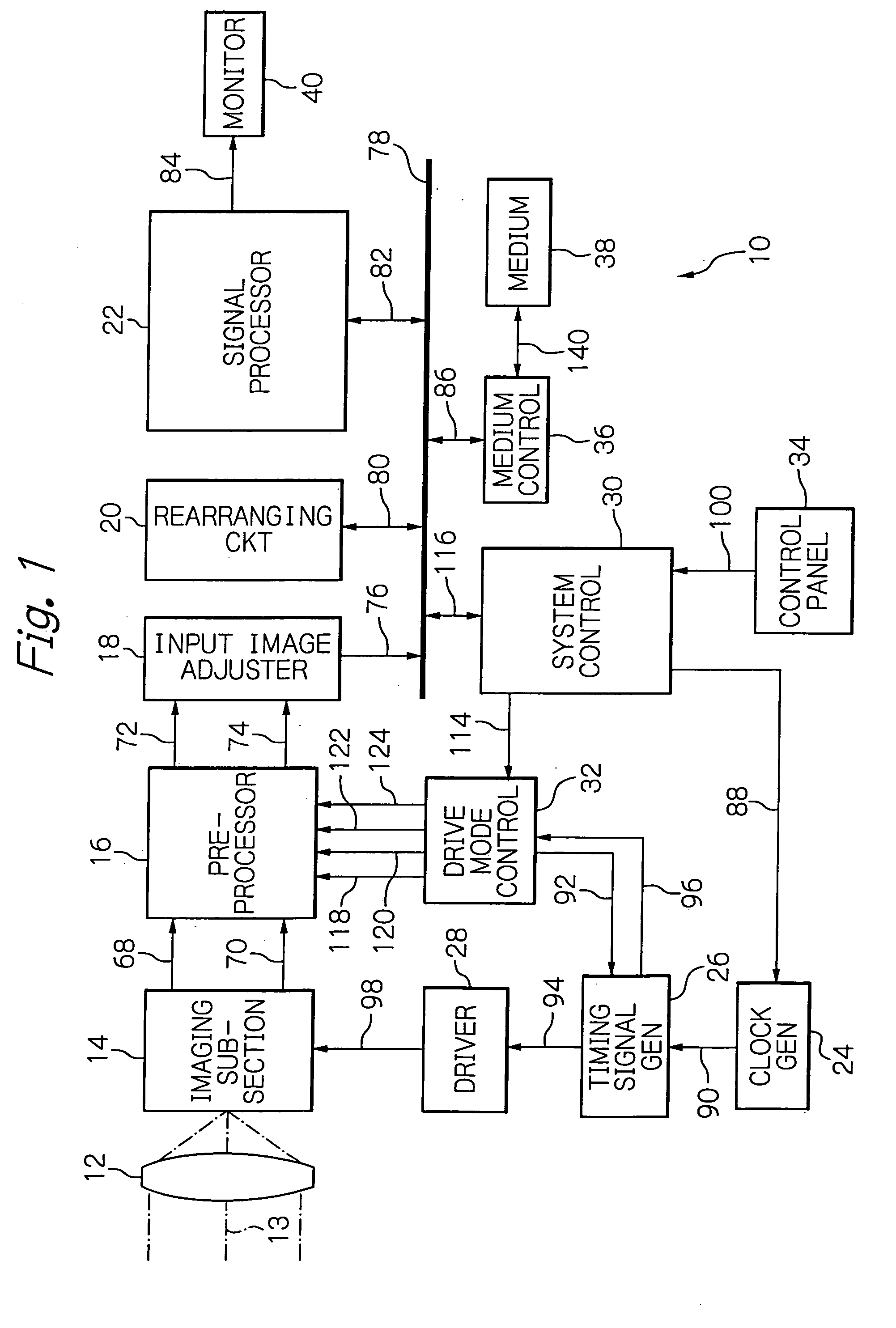
[0044] Referring to FIG. 1, the digital camera 10 includes an optical system 12, an imaging subsection 14, a preprocessor 16, an input image adjuster 18, a rearranging circuit 20, a signal processor 22, a clock generator 24, a timing signal generator 26, a driver 28, a system control 30, a drive mode control 32, a control panel 34, a medium control 36, a recording medium 38, and a display monitor 40, which are interconnected as illustrated.

[0045] The optical system 12 has a function of conducting incident light 13 from a subject field into the imaging subsection 14 in response to the operation on the co...


PUM


Abstract

An image pickup apparatus includes a plurality of output channels and appropriately operates depending on use situation. The image pickup apparatus includes a system control for determining whether a condition is set on a resolution representing a first speed mode, a resolution representing a second speed mode faster than VGA (Video Graphics Array), or an HDTV (High Definition TeleVision) to generate a control signal depending on the determination result. The control signal controls a drive mode control. Under the control of a timing signal generator responsive to a control signal supplied from the drive mode control, an image sensor and a driver therefor provides image signals captured on two outputs or a single output. The drive mode control controls processing of the image signals in a preprocessor so as to correspond to the number of the output channels of the image sensor.

Description

BACKGROUND OF THE INVENTION [0001] 1. Field of the Invention [0002] The present invention relates to an image pickup apparatus, and more specifically to an image pickup apparatus that uses an image sensor having a plurality of output stages to enable signal charges to be read out at a high transfer rate. [0003] 2. Description of the Background Art [0004] To achieve an image sensor enabling signal charges to be read out at a high transfer rate, an image sensor or an image pickup apparatus having a plurality of outputs or horizontal transfer paths is proposed in Japanese patent laid-open publication Nos. 2004-194023 and 103421 / 1999. The former, '023 publication, discloses an image pickup apparatus in which signal charges are read out only from a selected portion of its photosensitive array and are then transferred to be developed from two output amplifiers in the form of analog signals. The latter, '421 publication, discloses a solid-state image sensor and a driving method thereof in ...

Claims


Application Information

Patent Timeline
IPC IPC(8): H04N1/04
CPCH04N3/1575H04N25/42H04N25/713H04N25/73
Inventor SUEMOTO, KAZUNORIIKEDA, KATSUMI
Owner FUJIFILM CORP
Why Eureka
Try Eureka