
Automatic transaction device and automatic transaction method

a technology of automatic transaction and automatic transaction method, which is applied in the direction of atm details, complete banking machines, instruments, etc., can solve the problem that the person in front of the automatic transaction device will make a dishonest transaction by tampering

Active Publication Date: 2015-04-23
OKI ELECTRIC IND CO LTD
View PDF13 Cites 1 Cited by
  • Summary
  • Abstract
  • Description
  • Claims
  • Application Information

AI Technical Summary

Benefits of technology

The present invention helps prevent the automatic transaction device from doing unnecessary work when there is a problem with the shutter.

Problems solved by technology

This is because, when a resetting operation is carried out by remote control or automatically and the shutter is opened and closed, there is the concern that a person in front of the automatic transaction device will make a dishonest transaction by tampering or the like.

Method used


Image

  • Automatic transaction device and automatic transaction method
  • Automatic transaction device and automatic transaction method
  • Automatic transaction device and automatic transaction method

Examples


first embodiment

1. First Embodiment

(1-1. Summary of Automatic Transaction System)

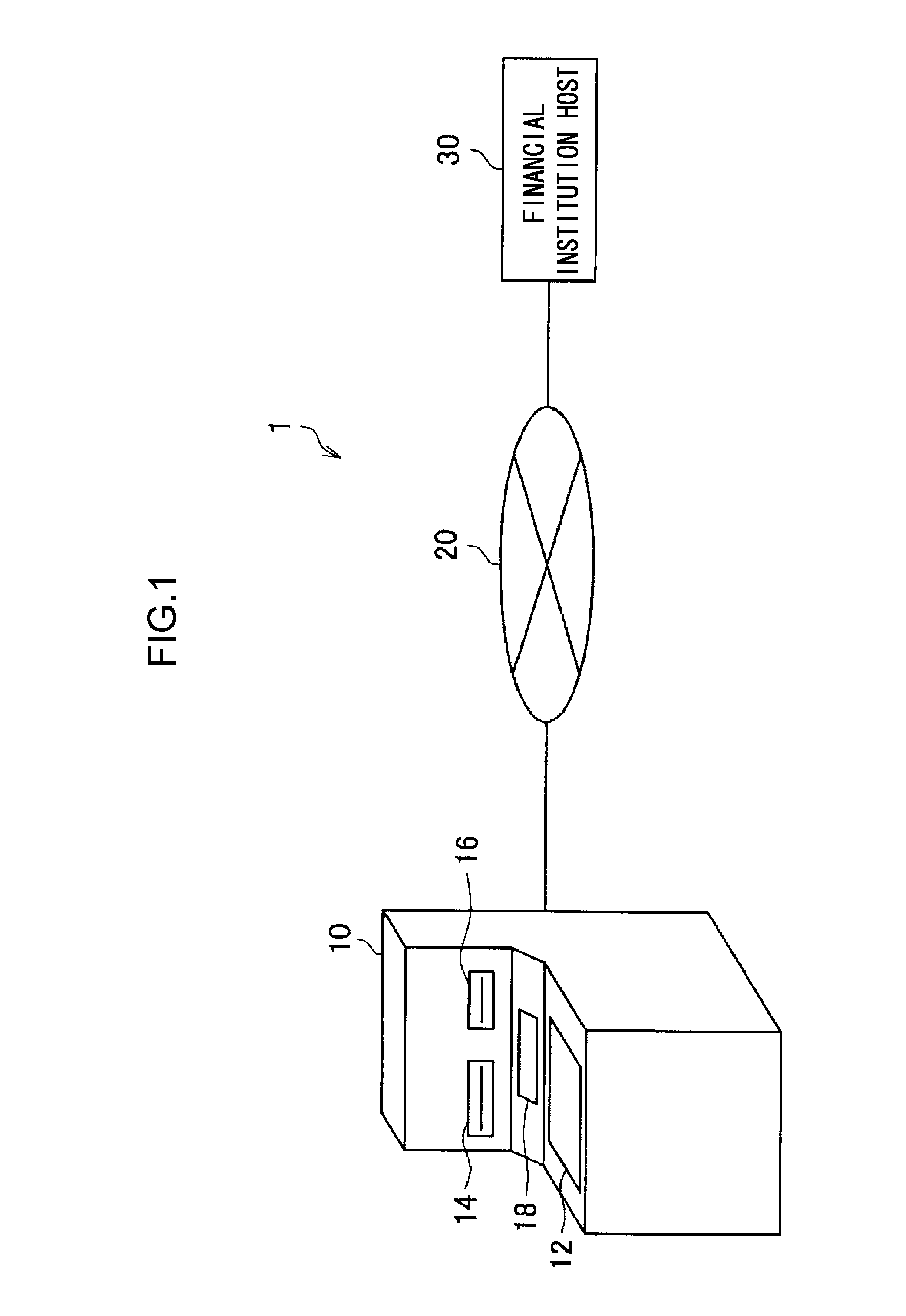
[0033]A summary of an automatic transaction system 1 relating to a first embodiment is described with reference to FIG. 1.

[0034]FIG. 1 is a drawing for explaining the schematic structure of the automatic transaction system 1 relating to the first embodiment. As shown in FIG. 1, the automatic transaction system 1 has an automatic transaction device 10, a private network 20, and a financial institution host 30.

[0035]The automatic transaction device 10 is a customer-operated terminal that executes cash transactions on the basis of operations by a customer of the financial institution. The automatic transaction device 10 is set within various facilities such as, for example, an office of the financial institution, a convenience store, a station, or the like.

[0036]The automatic transaction device 10 has a customer operation / display portion 12, a passbook insertion opening 14, a card insertion opening 16, and a customer inte...

second embodiment

2. Second Embodiment

(2-1. Example of Functional Structure of Control Device)

[0072]FIG. 7 is a block diagram showing an example of the functional structure of the control device 132 relating to a second embodiment. As shown in FIG. 7, the control device 132 relating to the second embodiment has the opened / closed sensing section 202, the cash sensing section 204, the cash processing section 206, the trouble information acquiring section 208, the person sensing section 210, the control section 212, a mode setting section 220, and a number-of-times information acquiring section 222.

[0073]The opened / closed sensing section 202, the cash sensing section 204, the cash processing section 206, the trouble information acquiring section 208 and the person sensing section 210 relating to the second embodiment have functions that are similar to the first embodiment that was explained in FIG. 4, and therefore, detailed description thereof is omitted.

[0074]The mode setting section 220 sets an opera...


PUM


Abstract

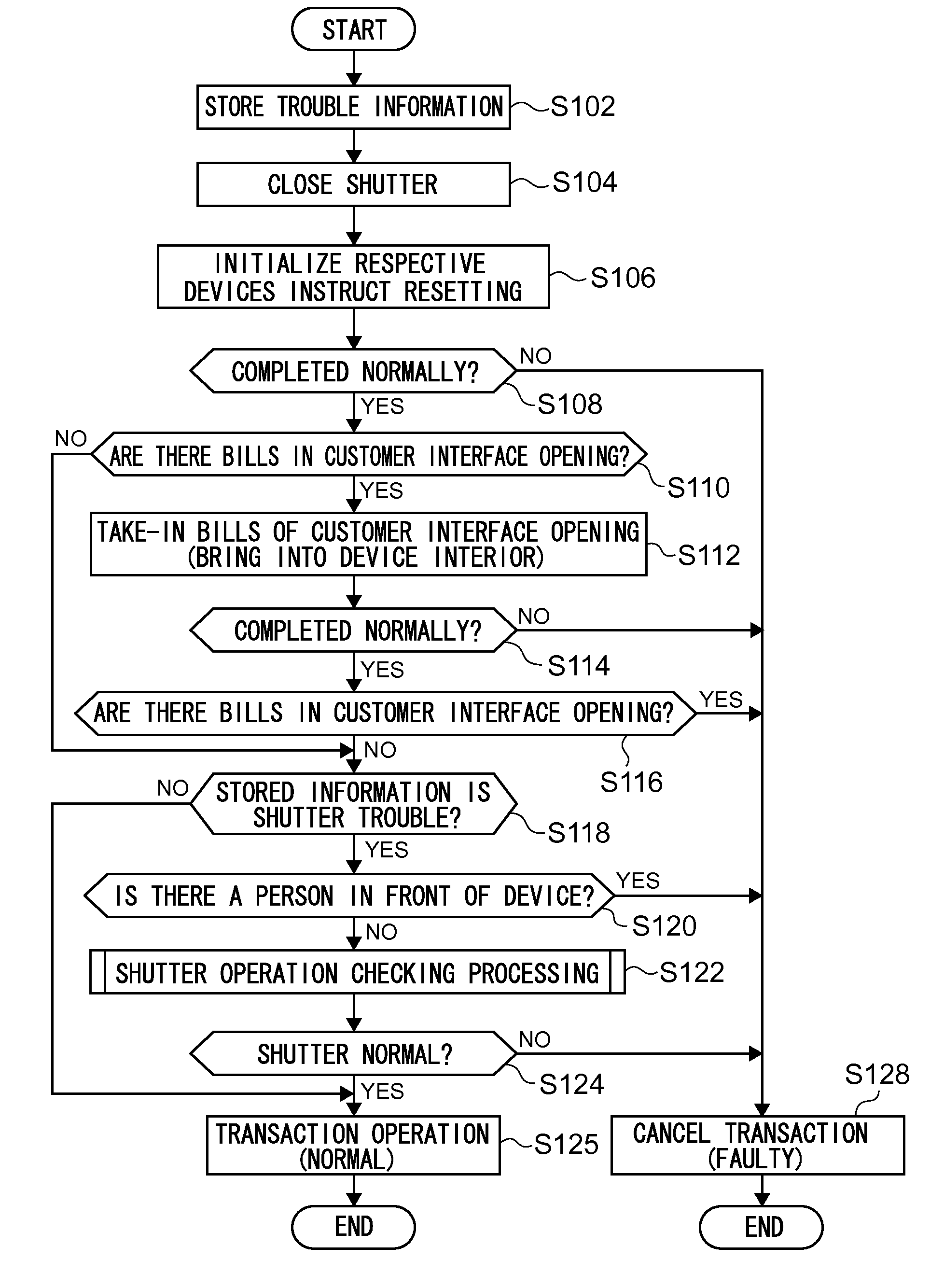
The objective of the present invention is to provide an automatic transaction device capable of suppressing wasteful operation of the automatic transaction device when a shutter failure has occurred. The present invention is an automatic transaction device that performs transactions related to cash, and is characterized by including: a deposit / withdrawal slot for depositing / withdrawing cash; an opening / closing member that is capable of opening and closing the deposit / withdrawal slot by way of movement; an opened / closed detection unit that detects the opened / closed state of the opening / closing member; and a control unit that opens and closes the opening / closing member at the time of a reset operation of the automatic transaction device to perform operation verification processing, causes detection of the opened / closed state of the opening / closing member after the operation verification processing, and if it is determined that the opened / closed state is abnormal, aborts the transaction.

Description

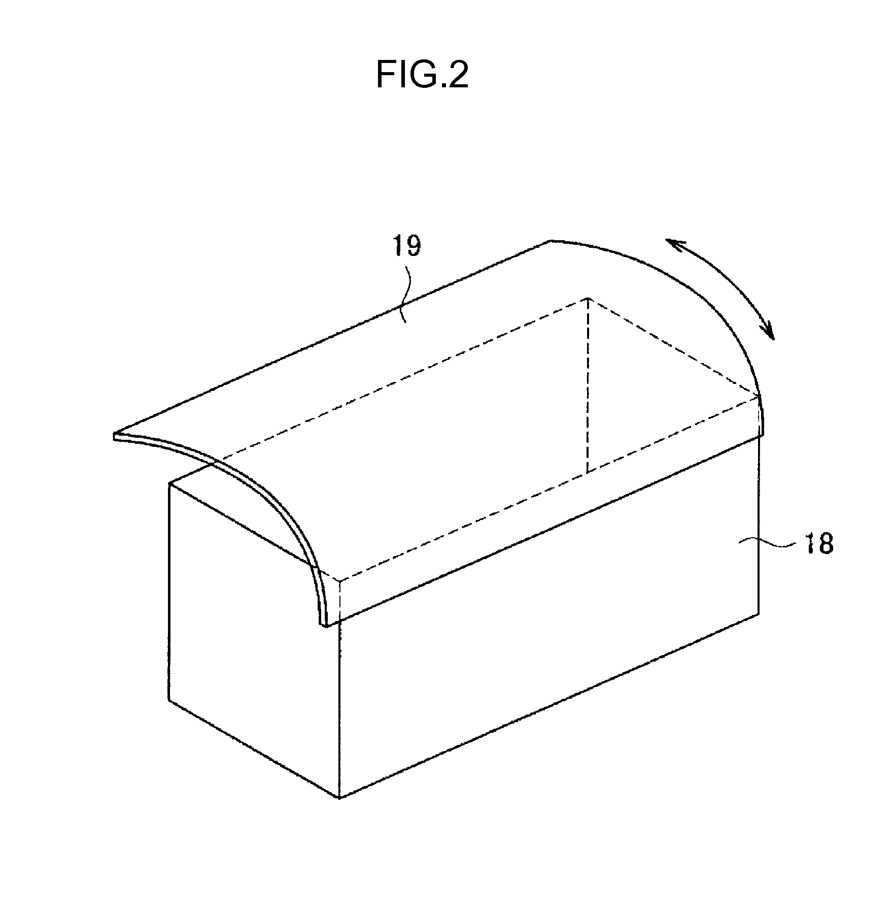
TECHNICAL FIELD[0001]The present invention relates to an automatic transaction device and an automatic transaction method.BACKGROUND ART[0002]Automatic transaction devices, that are exemplified by ATMs (Automated teller machines) of financial institutions, are set in a branch of a financial institution such as a bank or the like, or in a store such as a convenience store or the like. A customer can carry out transactions such as deposits, withdrawals, balance inquiries, and the like by carrying out various types of operations at a display screen that is displayed on the automatic transaction device.[0003]The automatic transaction device has a transfer opening (also called a customer interface opening) for carrying out transfer of cash (e.g., bills) with customers. Further, a shutter that can open and close is provided at the transfer opening. The shutter is usually closed, but, due to the shutter opening at the time when cash is transferred to / from a customer, the customer can inser...

Claims


Application Information

Patent Timeline
Patent Type & Authority Applications(United States)
IPC IPC(8): G07D11/00G07F19/00
CPCG07D11/0042G07D11/0018G07F19/203G07F19/209G07D11/225G07D11/14G07D11/26
Inventor KOIDE, MASAICHI
Owner OKI ELECTRIC IND CO LTD
Learn More