
Multicarrier communication apparatus

a communication apparatus and multi-carrier technology, applied in diversity/multi-antenna systems, multi-frequency code systems, transmission path division, etc., can solve problems such as lowering the reception error rate, achieve peak suppression with ease, eliminate useless operations of demodulation processing and decoding processing circuits, and achieve the effect of reducing the number of errors

Inactive Publication Date: 2013-11-12
FUJITSU LTD
View PDF23 Cites 1 Cited by
  • Summary
  • Abstract
  • Description
  • Claims
  • Application Information

AI Technical Summary

Benefits of technology

[0036]According to the above-described technique, at least any one of the following effects and benefits are realized.
[0037](1) Since transmission halting processing is performed, upon occurrence of an unallowable (exceeding the threshold) peak in a multicarrier signal to be transmitted, to at least apart of the multiple series of transmission data (for example, transmission halting processing is sequentially performed in increasing order of precedence in the scheduling means or in increasing order of the width of the frequency band in use), it is possible to accomplish peak suppressing with ease without increasing the arithmetic operation scale, which is an issue in the previous art, while maintaining, for example, communication of users high in schedule precedence.
[0038](2) Further, since peak suppressing is controlled depending upon the presence or the absence of transmission data of each user (receiver), effects on bit errors and packet errors are not caused.
[0039](3) Still further, since the transmission data whose transmission has been temporarily halted for peak suppression is notified to the receiver end, useless operations of demodulation processing and decoding processing circuits can be eliminated. This significantly contributes to lowering of power consumption on the receiver end.
[0040](4) Furthermore, since a multicarrier signal from which at least a part of transmission data has been removed is generated beforehand in accordance with the above mentioned precedence (or the frequency band in use) and then a multicarrier signal whose peak becomes not larger than the threshold is selected as an object to be transmitted, it is possible to eliminate the necessity for regenerating a transmission multicarrier signal once again after peak evaluation performed, so that performance deterioration due to latency can be prevented.

Problems solved by technology

Thus, although a degree of peak suppressing effect can be obtained, a region non-continuous in time is generated in a sub-carrier as schematically shown in (4) and (5) of FIG. 18, so that generation of out-band radiation cannot be avoided and the orthogonal relationship between sub-carriers is lost, characteristic deterioration thereby being caused.
Further, as described in the above patent document 1, in the technique of puncturing a part of an information signal and inserting a peak suppressing signal thereinto, a bit error is caused in the punctured part, so that strong error correction processing is required for preventing lowering of the reception error rate.

Method used


Image

  • Multicarrier communication apparatus
  • Multicarrier communication apparatus
  • Multicarrier communication apparatus

Examples


first embodiment

[B] First Embodiment

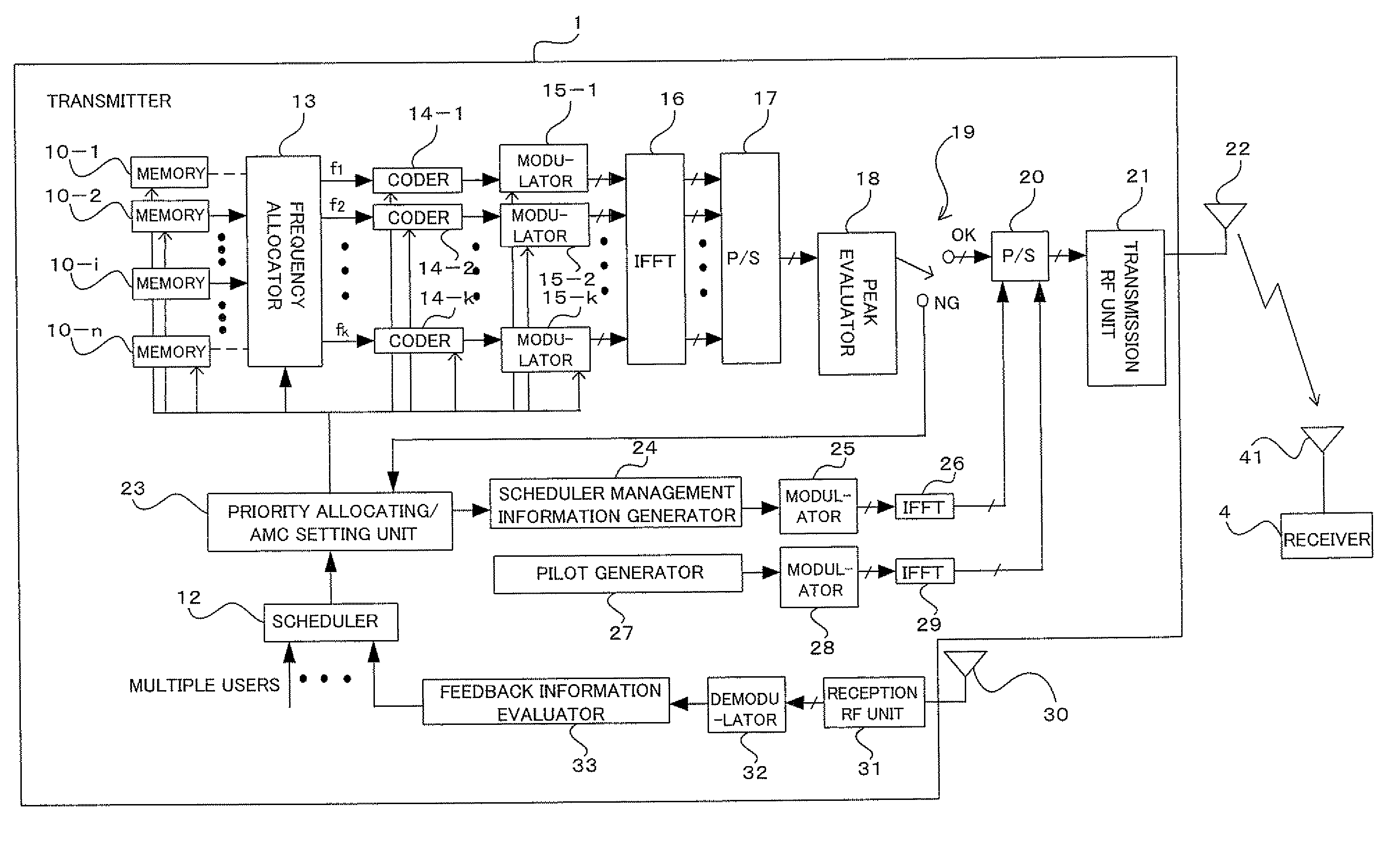
[0123]FIG. 4 is a block diagram illustrating a construction of a multicarrier (OFDM) transmission system according to a first embodiment with a focus on a transmitter (multicarrier communication apparatus); FIG. 5 is a diagram illustrating a construction of a multicarrier (OFDM) transmission system according to the first embodiment of the present invention with an attention paid to a receiver. For example, the transmitter 1 shown in FIG. 4 is applicable to base station apparatuses, and the receiver 4 shown in FIG. 5 is applicable to mobile terminal apparatuses. In this instance, hereinafter, the transmitter 1 will be also called the base station 1, and the receiver 4 will be also called the terminal 4. Further, the number of sub-carriers is assumed to be k (k is an integer equal to or larger than 2). Further, in FIG. 4, the wiring added with “ / ” indicates that an orthogonal multiplexed I-Q signal on a complex plane is transmitted.

[0124]As shown in FIG. 4, with a ...

second embodiment

[C] Second Embodiment

[0187]FIG. 13 is a block diagram illustrating the above described transmitter 1 according to a second embodiment. The construction of the transmitter 1 of FIG. 13 differs from the construction of the transmitter 1 above described with reference to FIG. 4, in that the coder 14 and the modulator 15 are provided for the previous stage to the frequency allocator 13. That is, in the construction of the present example, adaptive modulation is performed for each user, not for each sub-carrier (or each sub-carrier group) shown in FIG. 4, before user data streams are mapped to sub-carriers.

[0188]In the present example, although adaptive modulation optimal for each sub-carrier (or each sub-carrier group) is not performed, the adaptive modulation scheme can be specified for each user, so that it is possible to reduce the amount of control information.

[0189]In this instance, in FIG. 13, the construction elements added thereto with reference characters the same as those alre...

third embodiment

[D] Third Embodiment

[0190]FIG. 14 is a block diagram illustrating a third embodiment of the above described transmitter 1. The construction of the transmitter 1 shown in FIG. 14 differs from that of the transmitter 1 shown in FIG. 4, in that the block in the stage previous to the P / S converter 20 is replaced with a block including: multiple transmission signal generators 36-1 through 36-M; the multiple peak evaluators 18-1 through 18-M corresponding to the transmission signal generators 36-1 through 36-M, respectively; an optimal generation scheme evaluator 37; and a generation scheme notifying unit 38. In this instance, the construction elements added thereto with reference characters the same as those already described are the same as or similar to those already described unless otherwise described. In addition, the construction of the terminal 4 need not be different from that of the receiver 4 in the first embodiment (FIG. 5).

[0191]Here, as shown in FIG. 15 and FIG. 16, the tran...


PUM


Abstract

A multicarrier communication apparatus includes: a scheduler operable to schedule transmission opportunities of the plurality of series of transmission data in accordance with predetermined scheduling information; a peak evaluator to evaluate whether or not the peak of the multicarrier signal exceeds a predetermined threshold value; and a peak suppressing unit operable to halt transmission of at least some of the plurality of series of transmission data based on the scheduling information upon decision by said peak evaluator that the result of the evaluation exceeds the threshold value. This construction makes it possible to accomplish peak suppression with ease without increasing the arithmetic scale, like in the previous art, while maintaining communication of users high in scheduling precedence.

Description

[0001]This application is a continuation of International Application No. PCT / JP06 / 301534, filed Jan. 31, 2006, now pending, the contents of which are incorporated by reference.TECHNICAL FIELD[0002]The present invention relates to a multicarrier communication apparatus and a peak suppressing method for use in the same apparatus. For example, the present invention relates to technology for use in a system which transmits a multicarrier signal including more than one sub-carrier to which allocated are more than one series of transmission data.BACKGROUND ART[0003]Multicarrier transmission schemes such as OFDM (Orthogonal Frequency Division Multiplexing), that is, schemes in which a multicarrier signal, including more than one sub-carrier to which more than one series of transmission data is allocated, respectively, is transmitted, may cause an effect of non-linear distortion in an amplifier (power amplifier) since the larger the number of sub-carriers, the larger becomes a Peak to Aver...

Claims


Application Information

Patent Timeline
Patent Type & Authority Patents(United States)
IPC IPC(8): H04K1/10
CPCH04L5/0044H04L27/2614H04B2201/70706H04L5/0007H04L5/0058
Inventor YOKOYAMA, HITOSHI
Owner FUJITSU LTD
Learn More