Heat sink device with shielding member

Inactive Publication Date: 2007-04-19
HON HAI PRECISION IND CO LTD
View PDF8 Cites 64 Cited by
  • Summary
  • Abstract
  • Description
  • Claims
  • Application Information

AI Technical Summary

Benefits of technology

[0004] In an exemplary embodiment, a heat sink device includes a heat sink and a shielding member. The heat sink defines a receiving groove. The shielding member includes a fixing plate received in the receiving groo

Problems solved by technology

Therefore, the effective performance of the electronic component may be interrupted, obstructed, or degraded by EMI.
Ther

Method used


Image

  • Heat sink device with shielding member
  • Heat sink device with shielding member
  • Heat sink device with shielding member

Examples


Embodiment Construction

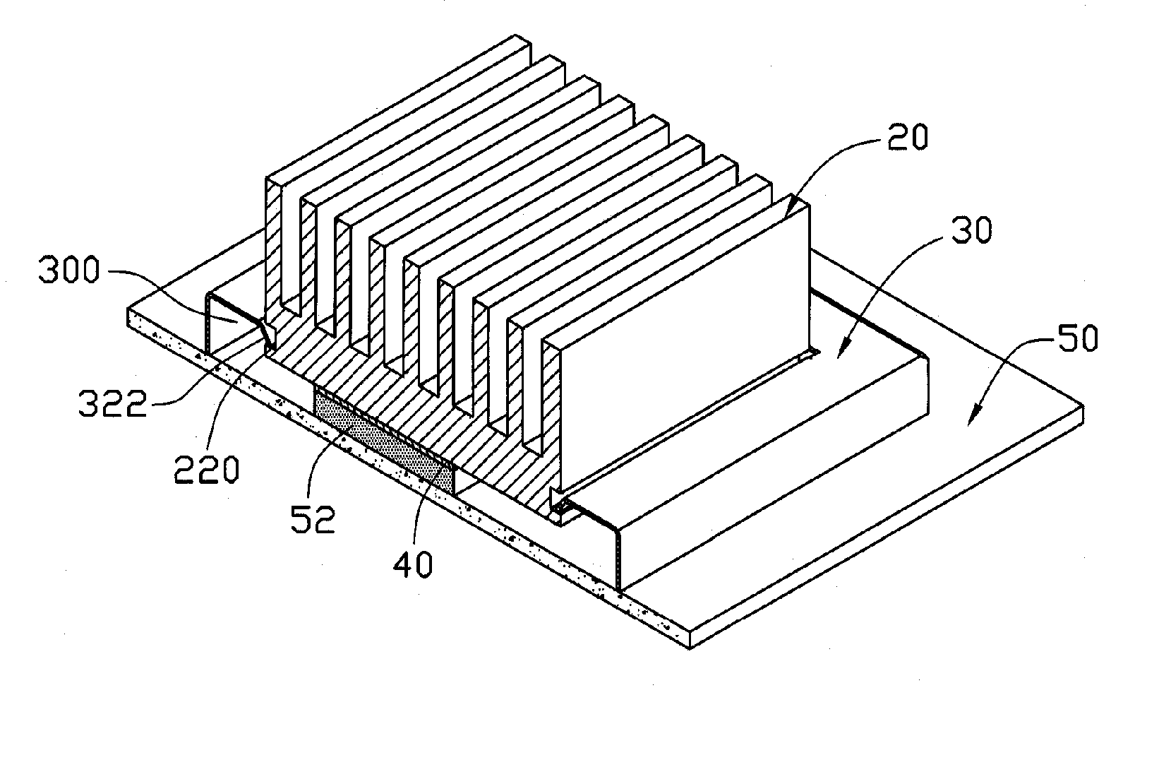
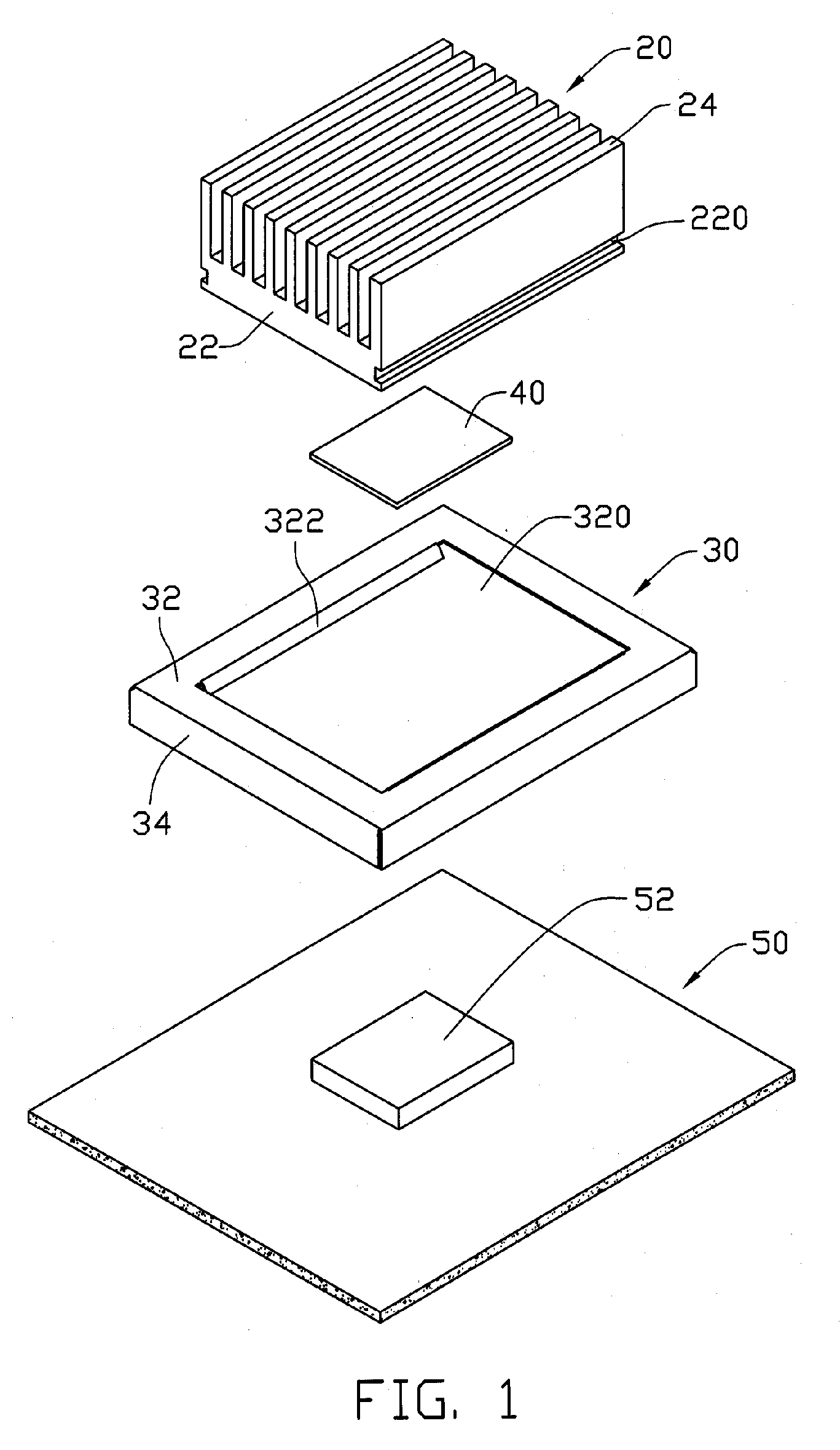
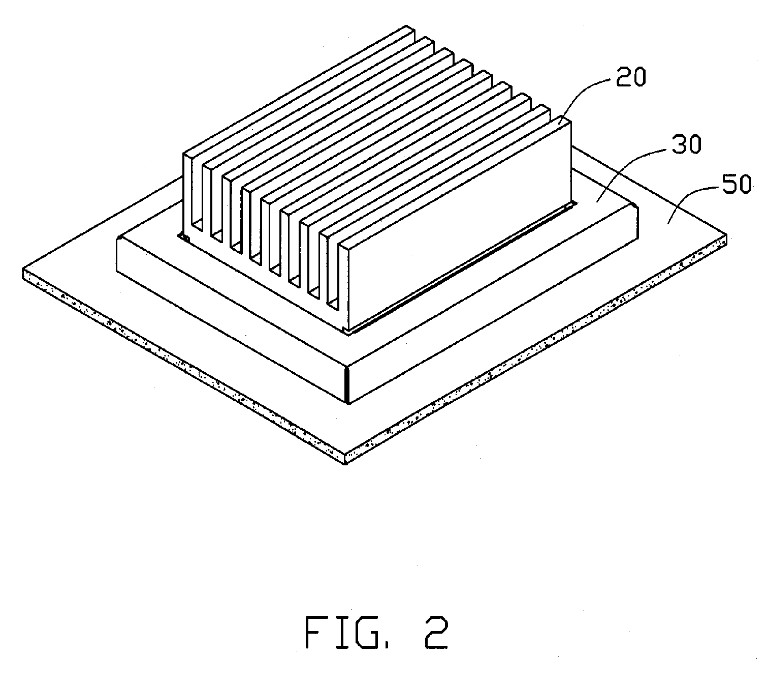
[0010] Referring to FIG. 1, a heat sink device of an exemplary embodiment of the present invention is mounted on a circuit board 50 including an electronic component 52, such as a printed circuit board. The heat sink device comprises a heat sink 20, a shielding member 30, and a heat conducting film 40.

[0011] The heat sink 20 includes a plurality of heat fins 24 and a base 22. The heat fins 24 are integrally formed with the base 22, and are perpendicular to the base 22. Two receiving grooves 220 are respectively defined in opposite sidewalls of the base 22. In an alternative embodiment, the receiving grooves 220 can be respectively defined in the two outboard heat fins 24.

[0012] The shielding member 30 is used for providing EMI shielding to the electronic component 52. The shielding member 30 comprises a top wall 32, and four sidewalls 34 each perpendicular to the top wall 32. The top wall 32 and the sidewalls 34 cooperatively surround a receiving portion 300. The electronic compon...


PUM


Abstract

A heat sink device includes a heat sink (20) and a shielding member (30). The heat sink defines a receiving groove (220). The shielding member includes a fixing plate (322) received in the receiving groove, and a receiving portion (300) for receiving an electronic component. The heat sink device not only protects the electronic component from EMI, but also effectively dissipates heat generated by the electronic component.

Description

1. FIELD OF THE INVENTION [0001] The present invention relates to heat sinks, and particularly to a heat sink device with a shielding member that provides electromagnetic interference (EMI) shielding. 2. DESCRIPTION OF RELATED ART [0002]FIG. 4 is an isometric view of a conventional heat sink 40. The heat sink 40 can be mounted on an electronic component (not shown). The heat sink 40 comprises a plurality of heat fins 42 for dissipating heat generated by the electronic component. However, the electronic component generally comprises high frequency circuits (HFC), digital signal circuits (DSC), and analog signal circuits (ASC). Electromagnetic Interference (EMI) often occurs between neighboring electronic components due to inductive coupling. In addition, the heat sink 40 does not shield the electronic component from external EMI. Therefore, the effective performance of the electronic component may be interrupted, obstructed, or degraded by EMI. [0003] Therefore, a heretofore unaddres...

Claims


Application Information

Patent Timeline
IPC IPC(8): H05K7/20
CPCH01L23/367H01L23/3675H01L23/4093H01L23/552H05K9/0032H01L2924/0002H01L2924/00H05K7/2039
Inventor LIANG, JEN-YU
Owner HON HAI PRECISION IND CO LTD
Why Eureka
Try Eureka