Device for transmitting and receiving

Active Publication Date: 2007-04-19
ATMEL CORP
View PDF10 Cites 11 Cited by
  • Summary
  • Abstract
  • Description
  • Claims
  • Application Information

AI Technical Summary

Benefits of technology

[0011] It is therefore an object of the present invention to provide a simple device for transmitting and receiving, which is cost-effective in its implementation and saves power during operation and which in particular has a low peak current consumption.

Problems solved by technology

It is a disadvantage hereby that in some of the time segments, in which, e.g., the transmitting / receiving unit has an increased power requirement, the control unit also requires a large amount of operating power.
Conversely, it cannot be ruled out that the transmitting / receiving unit requires a large amount of power, when the control unit also has an increased demand.
The peak currents resulting from this increase not only the average power requirement of the transmitting / receiving device, but disadvantageously may require larger dimensioning of the power supply unit (battery).

Method used


Image

  • Device for transmitting and receiving
  • Device for transmitting and receiving
  • Device for transmitting and receiving

Examples


Embodiment Construction

[0028] In the figures, the same and functionally identical elements and signals, if not specified otherwise, are provided with the same reference characters.

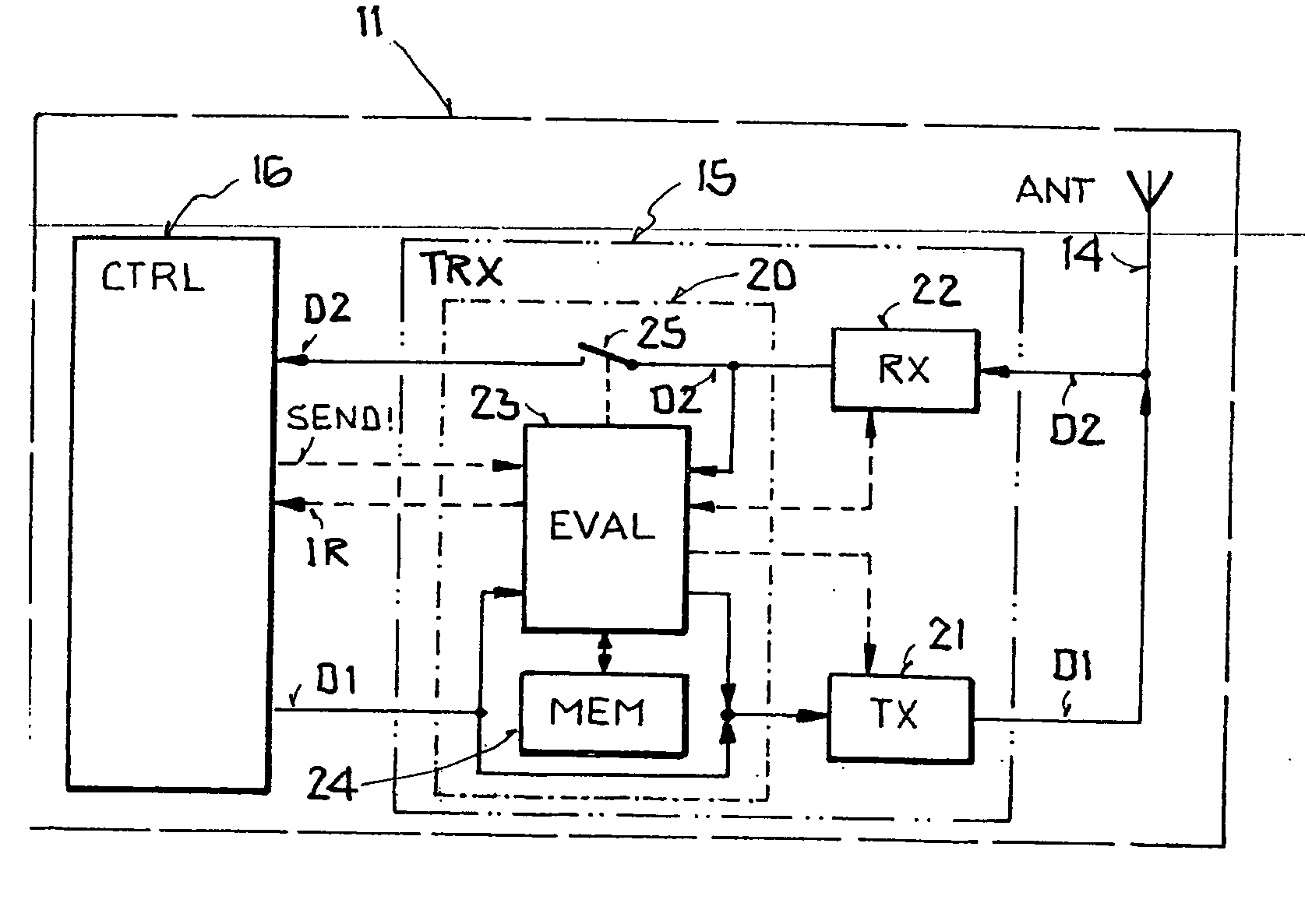
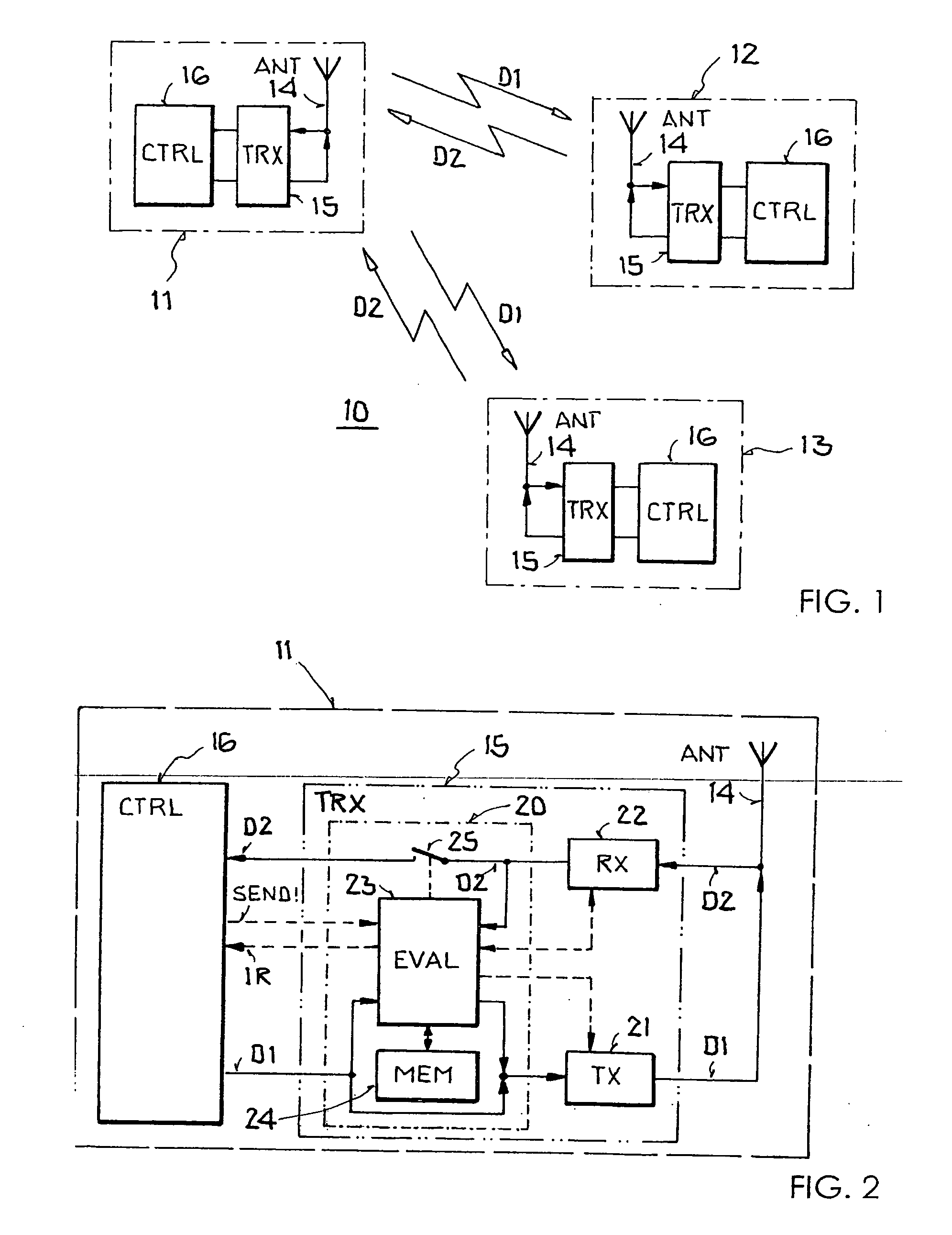
[0029]FIG. 1 shows an example of a WPAN data transmission system 10 according to the communication standard IEEE 802.15.4. It comprises three transmitting / receiving devices 11-13 in the form of stationary or mobile devices, which exchange information in a wireless manner by radio signals. The transmitting / receiving device 11 is a full-function device, which takes on the function of the WPAN coordinator, whereas transmitting / receiving devices 12, 13 are reduced-function devices, which are assigned to the full-function device 11 and can only exchange data with said device. Apart from the star network topology depicted in FIG. 1, in which bidirectional data transmission can only occur between one of the reduced-function devices 12, 13 and the full-function device 11, but not between the reduced function devices 12, 13, the standar...


PUM


Abstract

A device for transmitting and receiving is disclosed that includes: a) an antenna, b) a transmitting / receiving unit for transmitting and receiving data according to a communications standard, which has a transmitting unit, connected to the antenna, for transmitting first data frames to a second transmitting / receiving device and a receiving unit, connected to the antenna, for receiving second data frames from the second transmitting / receiving device, and c) a control unit, connected to the transmitting / receiving unit for controlling the transmitting / receiving unit, whereby the control unit is designed (c1) to instruct the transmitting / receiving unit to transmit a first data frame and (c2) to receive the second data frame from the transmitting / receiving unit. According to the invention, the transmitting / receiving unit has a controller, which is connected to the receiving unit and the control unit and is designed d) to evaluate a second data frame, received by the receiving unit within a predefined time interval after the transmission of the first data frame, and to determine whether the second data frame contains an acknowledgment message for the successful receipt of the first data frame by the second transmitting / receiving device, and e) not to relay the second data frame to the control unit, if it is determined that it contains the acknowledgment message.

Description

[0001] This nonprovisional application claims priority under 35 U.S.C. § 119(a) on German Patent Application No. DE 102005049931, which was filed in Germany on Oct. 19, 2005, and which is herein incorporated by reference. BACKGROUND OF THE INVENTION [0002] 1. Field of the Invention [0003] The present invention relates to a device for transmitting and receiving. [0004] The invention falls within the field of data transmission. Although it can be used in principle in any digital communication system for bidirectional data transmission, the present invention and its underlying problem will be explained below with reference to a “ZigBee” communication system in accordance with IEEE 802.15.4. [0005] 2. Description of the Background Art [0006] So-called “Wireless Personal Area Networks” (WPANs) can be used for the wireless transmission of information over relatively short distances (about 10 m). In contrast to “Wireless Local Area Networks” (WLANs), WPANs require little or even no infrast...

Claims


Application Information

Patent Timeline
IPC IPC(8): H04L27/00
CPCH04L1/1867H04L1/1887H04W88/02H04W52/0229Y02D30/70
Inventor FERCHLAND, TILOMENNENGA, MENNOPOEGEL, FRANKROEMER, ATTILA
Owner ATMEL CORP
Why Eureka
Try Eureka