
Digital display system

Inactive Publication Date: 2005-07-19
BEAUTY UP
View PDF2 Cites 28 Cited by
  • Summary
  • Abstract
  • Description
  • Claims
  • Application Information

AI Technical Summary

Benefits of technology

[0012]Another objective of the invention is to provide a novel digital display system having a digital board with a large-scale panel, and the digital board can be fabricated by a currently available jig, thereby making fabrication processes cost-effective to implement without additionally increasing costs for making a newly designed jig.
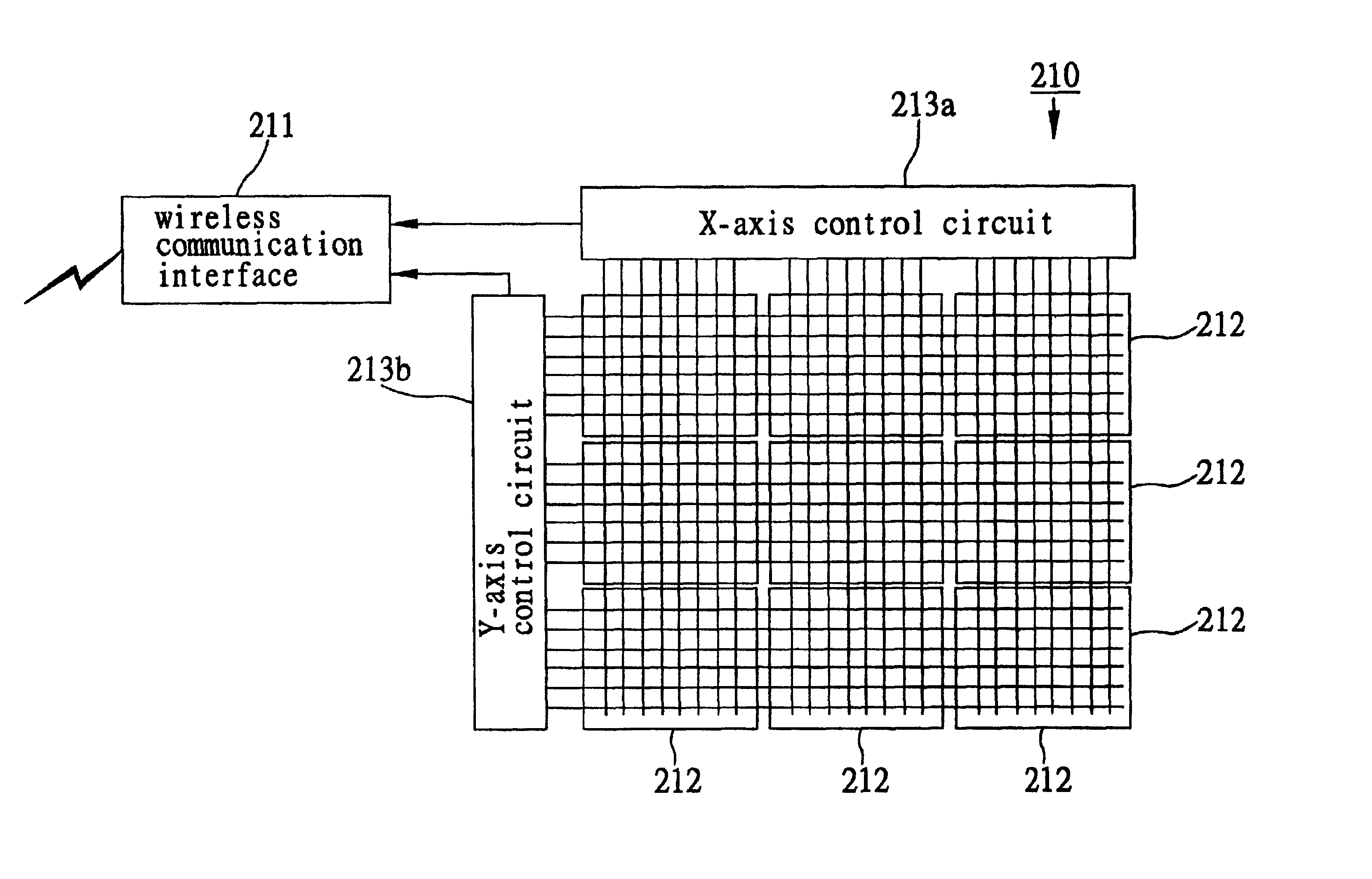
[0015]The invention is characterized in provision of a digital board composed of a plurality of currently-available printed circuit boards, wherein each pair of adjacent printed circuit boards are electrically interconnected by a plurality of conductive coupling wires, so as to integrally form a large-scale panel for the digital board. This characteristic feature allows the digital board to be simply fabricated by a currently used jig and flexibly enlarged in dimension according to practical requirements without increasing costs for developing a newly designed jig, thereby making fabrication processes cost-effective to implement.

Problems solved by technology

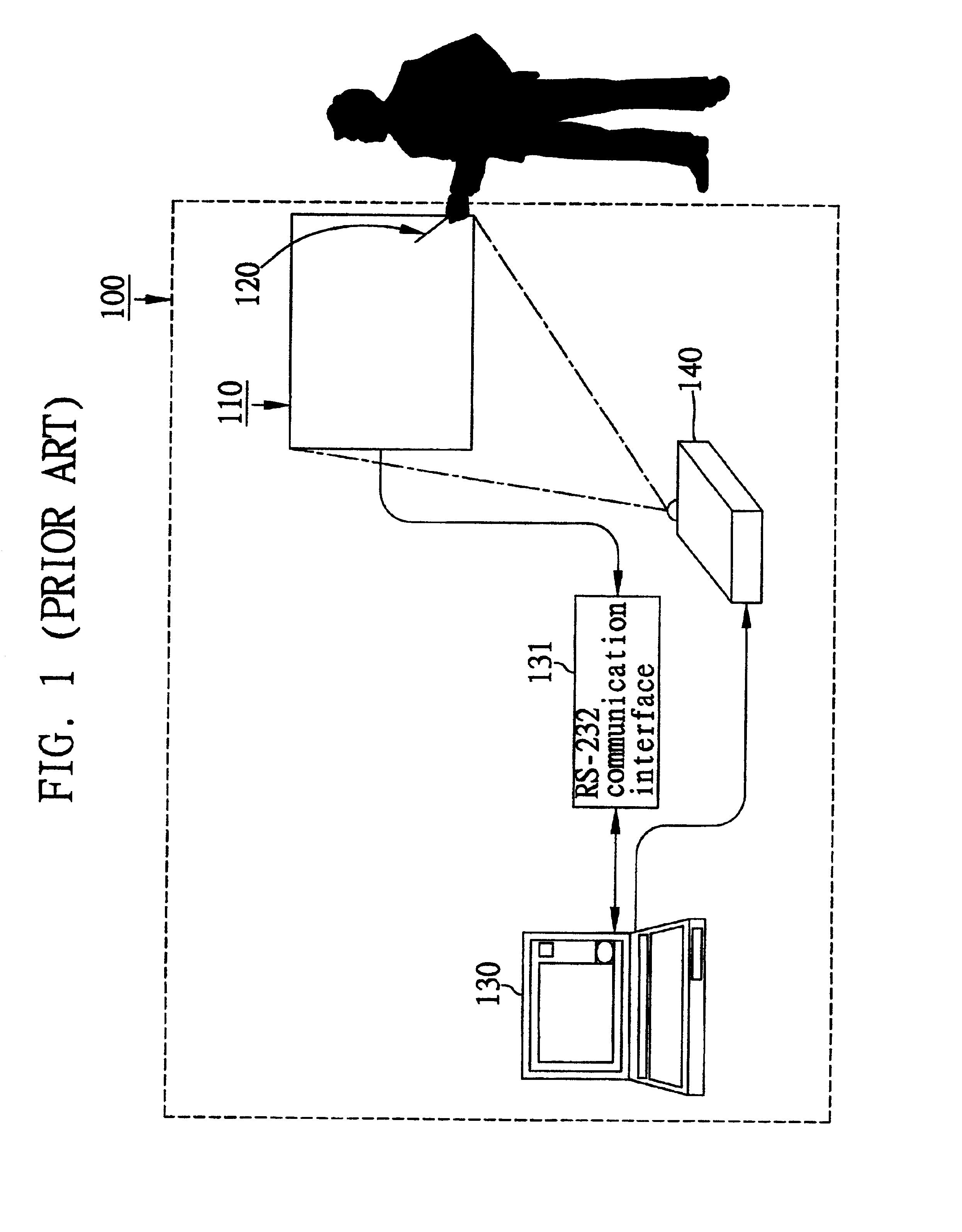
However, in practical operation of the above conventional digital display system 100, two significant drawbacks are elicited.
The second drawback is that, the digital board 110 is dimensioned regularly with its single piece of panel as 4:3 and 16:9, which respectively provides 1024*768 and 800*600 resolution.
This would undesirably increase labor and costs of manufacture, whereas each jig can only be suitably applied for fabricating a particularly fixed-sized digital board, making fabrication processes greatly cost-ineffective to implement.

Method used


Image

  • Digital display system
  • Digital display system
  • Digital display system

Examples


Embodiment Construction

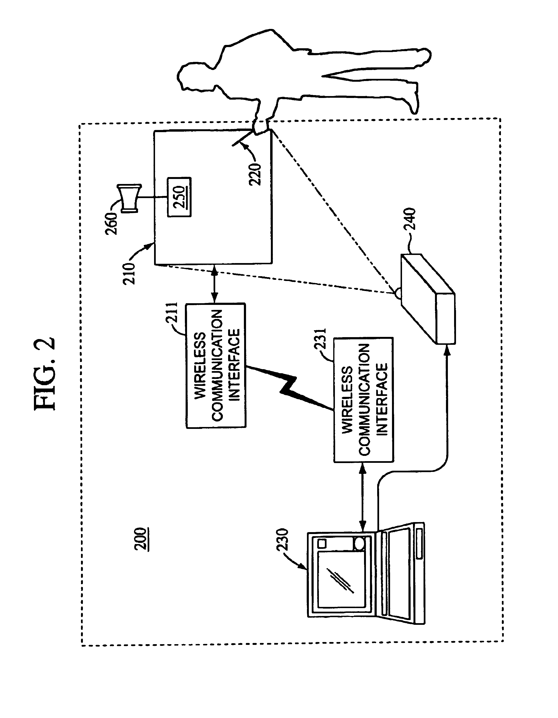
[0022]The following description is made with reference to FIGS. 2 to 4 for depicting preferred embodiments of a digital display system of the present invention.

[0023]First referring to FIG. 2, the digital display system 200 of the invention is basically configured at least including: (a) a digital board 210; (b) a touch pen 220; and (c) a computer platform 230. The digital board 210 is provided with a large-scale panel and a wireless communication interface 211 of particular wireless communication protocol, such as standard IrDA (infrared data association) wireless communication interface. The computer platform 230 is also provided with a wireless communication interface 231 of the same wireless communication protocol. The wireless communication interfaces 211, 231 are correlated with frequency correspondence to each other, allowing data to be transmitted in a fixed-frequency manner between the wireless communication interfaces 211, 231. Moreover, the digital display system 200 of t...


PUM


Abstract

A digital display system is proposed, which is characterized in provision of a digital board composed of a plurality of currently-available printed circuit boards, wherein each pair of adjacent printed circuit boards are electrically interconnected by a plurality of conductive coupling wires, so as to integrally form a large-scale panel for the digital board. This characteristic feature allows the digital board to be simply fabricated by a currently used jig and flexibly enlarged in dimension according to practical requirements without increasing costs for developing a newly designed jig, thereby making fabrication processes cost-effective to implement. Moreover, the above digital display system can be connected to a computer platform through a wireless communication interface, whereby pixel coordinate signals generated from the digital board can be wirelessly transferred to the computer platform for subsequent manipulation; therefore, this digital display system is relatively more convenient to use than prior art technology.

Description

FIELD OF THE INVENTION[0001]The present invention relates to digital display systems, and more particularly, to a digital display system providing a large-scale digital board by which data can be touch-controlled and transmitted through wireless communication to a computer platform.BACKGROUND OF INVENTION[0002]A digital board is customarily referred to as an electronic board, which allows a user to manually write on the board by using a touch pen. The digital board can be further connected to a computer platform by which words or letters written on the board are transformed into graphic files or directly printed out by a printer. This makes the digital board greatly suitable for use in a conference or meeting, and data or information provided on the digital board from a speaker can be promptly recorded down to be later used as reference. Moreover, the digital board can also cooperate with a projector for projecting data displayed on a screen of the computer platform onto the digital...

Claims


Application Information

Patent Timeline
IPC IPC(8): G06K11/06G06F3/033G09G5/00G06F3/03G06F3/046G06F3/041G06F3/048
CPCG06F3/0488
Inventor CHOU, HSIEN-CHUNG
Owner BEAUTY UP
Learn More