Method for synthesizing intermediate image using mesh based on multi-view square camera structure and device using the same and computer-readable medium having thereon program performing function embodying the same

a technology of multi-view square and intermediate image, which is applied in image analysis, instruments, computing, etc., can solve the problems of insufficient vivid motion and reality, distortion of view, and difficulty in displaying a three-dimensional effect in a vertical direction, so as to achieve accurate disparity vector, reduce occlusion region, and generate easy

Active Publication Date: 2007-04-19
KOREA ELECTRONICS TECH INST
View PDF10 Cites 26 Cited by
  • Summary
  • Abstract
  • Description
  • Claims
  • Application Information

AI Technical Summary

Benefits of technology

[0023] It is an object of the present invention to provide a method for synthesizing intermediate image using mesh based on multi-view square camera structure and a device using the same and a computer-readable medium having thereon program performing function embodying the same wherein an accurate disparity vector may be obtained since a shared area is searched for a predetermined time interval using a distance matching and a synthesized image is generated for each area based thereon, an occlusion region is reduced by using three reference images, the synthesized image may be easily generated even for an image having a large disparity, and a converted outline may be accurately expressed, and a high three-dimensional effect may be represented due to the image conversion through the mesh based on a vertex of the outline.

Problems solved by technology

While the method somewhat provides a three-dimensional effect for an observer, the method does not provide a sufficient vivid motion and reality as in a person seeing an actual object.
However, in case of the radical camera arrangement, a distortion of view may occur when a multi-view image obtained from different cameras is displayed on a single screen.
However, the parallel camera arrangement is disadvantageous in that it is difficult to display a three dimensional effect in a vertical direction.
However, it is virtually impossible to transmit an entire multi-view image using a conventional compression algorithm through a conventional broadcast channel.
However, in accordance with the conventional intermediate image synthesizing method, it is difficult to synthesize the intermediate image because the occlusion region is largely generated when a distance between base-lines is large or an angle or a distance between cameras is increased.
Moreover, since the adaptive point extractor is applied to an entire object, an unnecessary depth map information and an excessive adaptive point data may be generated.
As a result, in the synthesis of the intermediate image, the occlusion region is largely increased and the occlusion region cannot be completely compensated using only the adaptive point extractor.
Moreover, since the adaptive point extractor is applied to the entire object, an excessive simulation time is required.
In accordance with Reference 2, while problems of a processing time for the MBS and an extension of a boundary line in the depth map are solved by the multi-resolution method employing multiple cameras placed in arbitrary position, the resolution of each pixel and an accurate depth map cannot be obtained when the position and the angle between the cameras are increased.
Moreover, in accordance the method, a long simulation time is required due to the unnecessary depth map since the depth map is generated through every camera for the single object and a necessary intermediate image is generated.
However, Korean Patent Application No. 10-2004-116703 is disadvantageous in that an operation time for obtaining the distance matching is very long and accuracy is low.
Moreover, when various algorithms are applied only to an area having a large disparity, it is difficult to maintain an object and a background in the image.

Method used


Image

  • Method for synthesizing intermediate image using mesh based on multi-view square camera structure and device using the same and computer-readable medium having thereon program performing function embodying the same
  • Method for synthesizing intermediate image using mesh based on multi-view square camera structure and device using the same and computer-readable medium having thereon program performing function embodying the same
  • Method for synthesizing intermediate image using mesh based on multi-view square camera structure and device using the same and computer-readable medium having thereon program performing function embodying the same

Examples


Embodiment Construction

[0037] A method for synthesizing intermediate image using mesh based on multi-view square camera structure and device using the same and computer-readable medium having thereon a program performing function embodying the same in accordance with the present invention will now be described in detail with reference to the accompanied drawings.

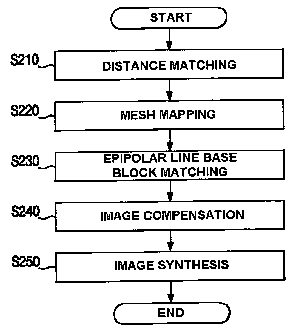
[0038]FIG. 4 is a flow chart illustrating a method for synthesizing an intermediate image using a mesh based on a multi-view square camera structure in accordance with the present invention.

[0039] As shown, the method for synthesizing an intermediate images using a mesh based on a multi-view square camera structure in accordance with the present invention comprises a distance-matching step S210, a mesh-mapping step S220, a epipolar line base block-matching step S230, a image-compensating step S240 and a image-synthesizing step S250.

[0040] In the distance-matching step S210, an overlapping area where an intermediate image to be synthesized and t...


PUM


Abstract

The present invention relates to an intermediate image synthesizing method using a mesh based on a multi-view square camera structure. In accordance with the present invention, an accurate disparity vector may be obtained since a shared area is searched for a predetermined time interval using a distance matching and a synthesized image is generated for each area based thereon, an occlusion region is reduced by using three reference images, the synthesized image may be easily generated even for an image having a large disparity, and a converted outline may be accurately expressed, and a high three-dimensional effect may be represented due to the image conversion through the mesh based on a vertex of the outline.

Description

RELATED APPLICATIONS [0001] The present disclosure relates to subject matter contained in priority Korean Application No. 10-2005-0098033 filed on 18 Oct. 2005, which is herein expressly incorporated by reference in its entirety. BACKGROUND OF THE INVENTION [0002] 1. Field of the Invention [0003] The present invention relates to a method for synthesizing intermediate image using mesh based on multi-view square camera structure and a device using the same and a computer-readable medium having thereon program performing function embodying the same, and more particularly, to a method for synthesizing intermediate image using mesh based on multi-view square camera structure and a device using the same and a computer-readable medium having thereon program performing function embodying the same wherein an accurate disparity vector may be obtained since a shared area is searched for a predetermined time interval using a distance matching and a synthesized image is generated for each area b...

Claims


Application Information

Patent Timeline
Patent Type & Authority Applications(United States)
IPC IPC(8): G06K9/00G06K9/36G06V10/10
CPCG06K9/20G06K2209/40G06T7/0075G06T7/593G06V10/10G06V2201/12
Inventor KIM, TAE-WANCHOI, BYEONG-HOKIM, JE-WOOSONG, HYOK
Owner KOREA ELECTRONICS TECH INST
Why Eureka
Try Eureka