Methods and apparatus for assembling composite structures

a composite structure and assembly method technology, applied in the field of composite structures, can solve the problems of premature failure of the flange, vibrational stress and load on the flange, and pull out of the fastener, and achieve the effect of facilitating the distribution of load

Active Publication Date: 2007-04-19
GENERAL ELECTRIC CO
View PDF39 Cites 40 Cited by
  • Summary
  • Abstract
  • Description
  • Claims
  • Application Information

AI Technical Summary

Benefits of technology

[0006] In a further aspect, a turbine engine assembly is provided. The turbine engine assembly includes a turbine engine, an engine casing, and at least one fastener. The engine casing includes a first casing section and a second casing section. The first casing section includes a first flange having an outer end portion, an inner end portion, and a body portion extending therebetween. The outer end portion extends from an end surface to the body portion. The first flange also includes a mating surface, an opposite load bearing surface, and an opening extending therebetween. The load bearing surface extends from the outer end over the outer end portion, the body portion, and the inner end portion. At least one of the outer end portion and the inner end portion has a partial frusto-conical cross-sectional shape such that a portion of the load bearin

Problems solved by technology

During operation of the engine, vibrational loading induced from the engine to the casing may induce vibrational stresses and loading to the flanges.
Over time, continued exposure to the vibrational loading may cause the fasteners to loosen, a conditio

Method used


Image

  • Methods and apparatus for assembling composite structures
  • Methods and apparatus for assembling composite structures
  • Methods and apparatus for assembling composite structures

Examples


Embodiment Construction

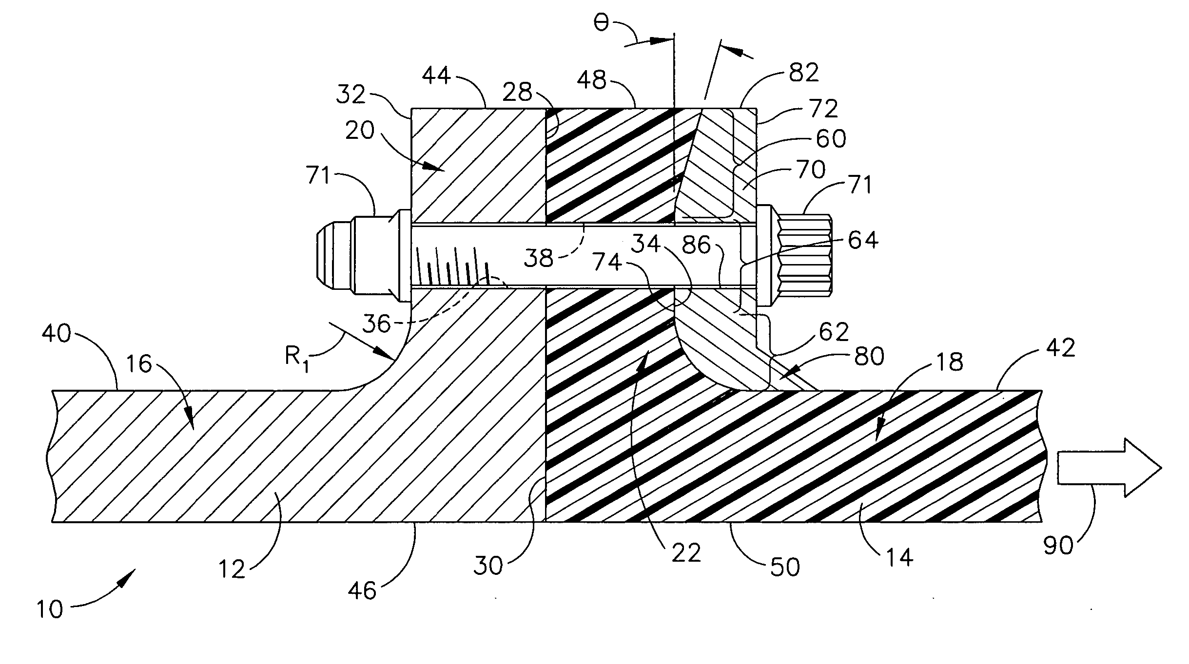
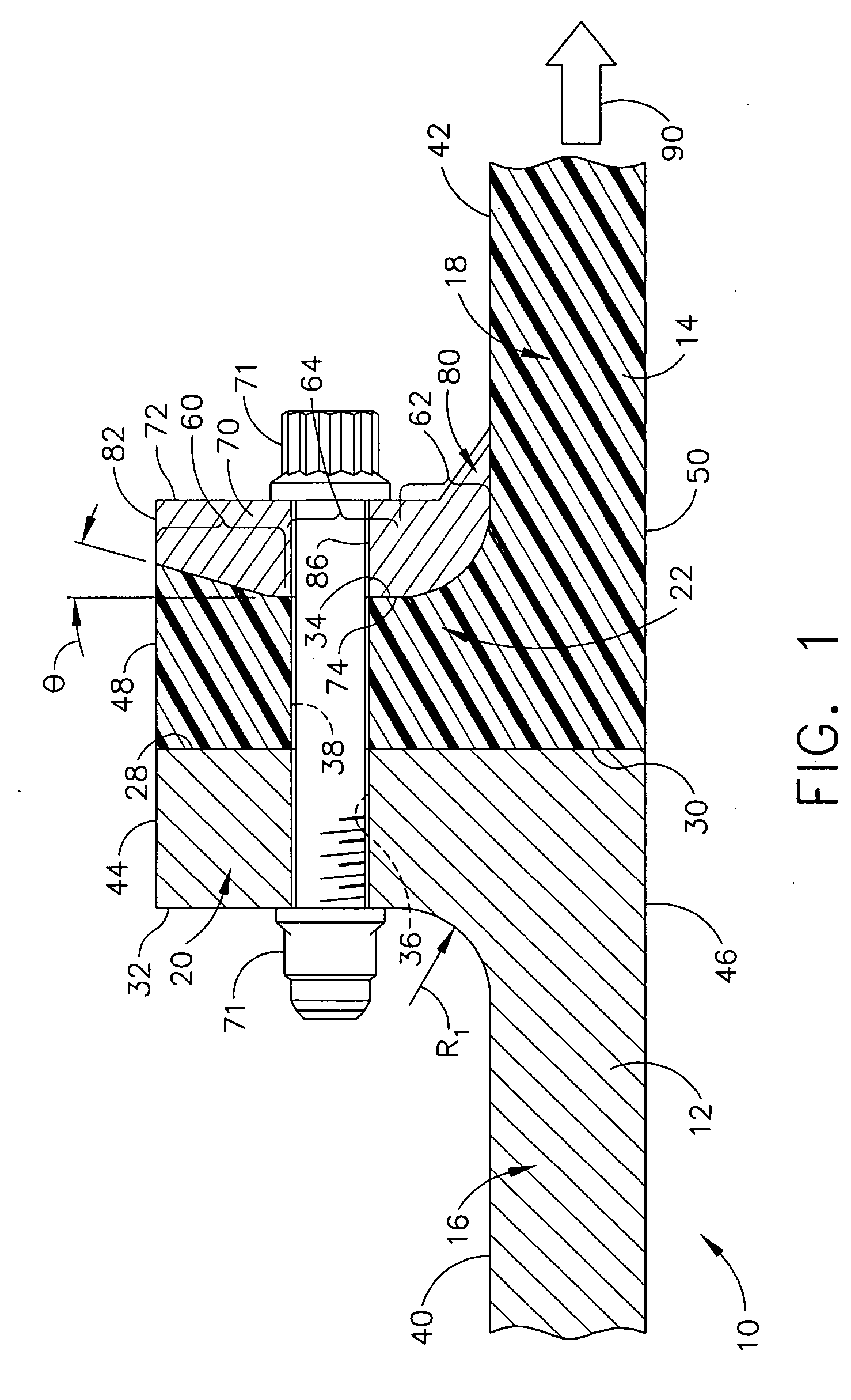
[0011]FIG. 1 is a side view of an exemplary embodiment of a coupling assembly 10 that may be used to fasten a pair of components 12 and 14 together. In the exemplary embodiment, components 12 and 14 are casing sections coupled together for use with a turbine engine assembly (not shown). Coupling assembly 10 is not limited to being used with turbine casing components 12 and 14, but rather coupling assembly 10 may be used to couple any adjacent components together as described herein. Accordingly, the specific size, shape, and configuration of coupling assembly 10, as described and / or illustrated herein, is exemplary only. Accordingly, the specific size, shape, and / or configuration of coupling assembly 10 generally, as well as portions thereof, may be selected to accommodate other components than engine casing sections 12 and 14. In the exemplary embodiment, component 14 is fabricated from a composite material.

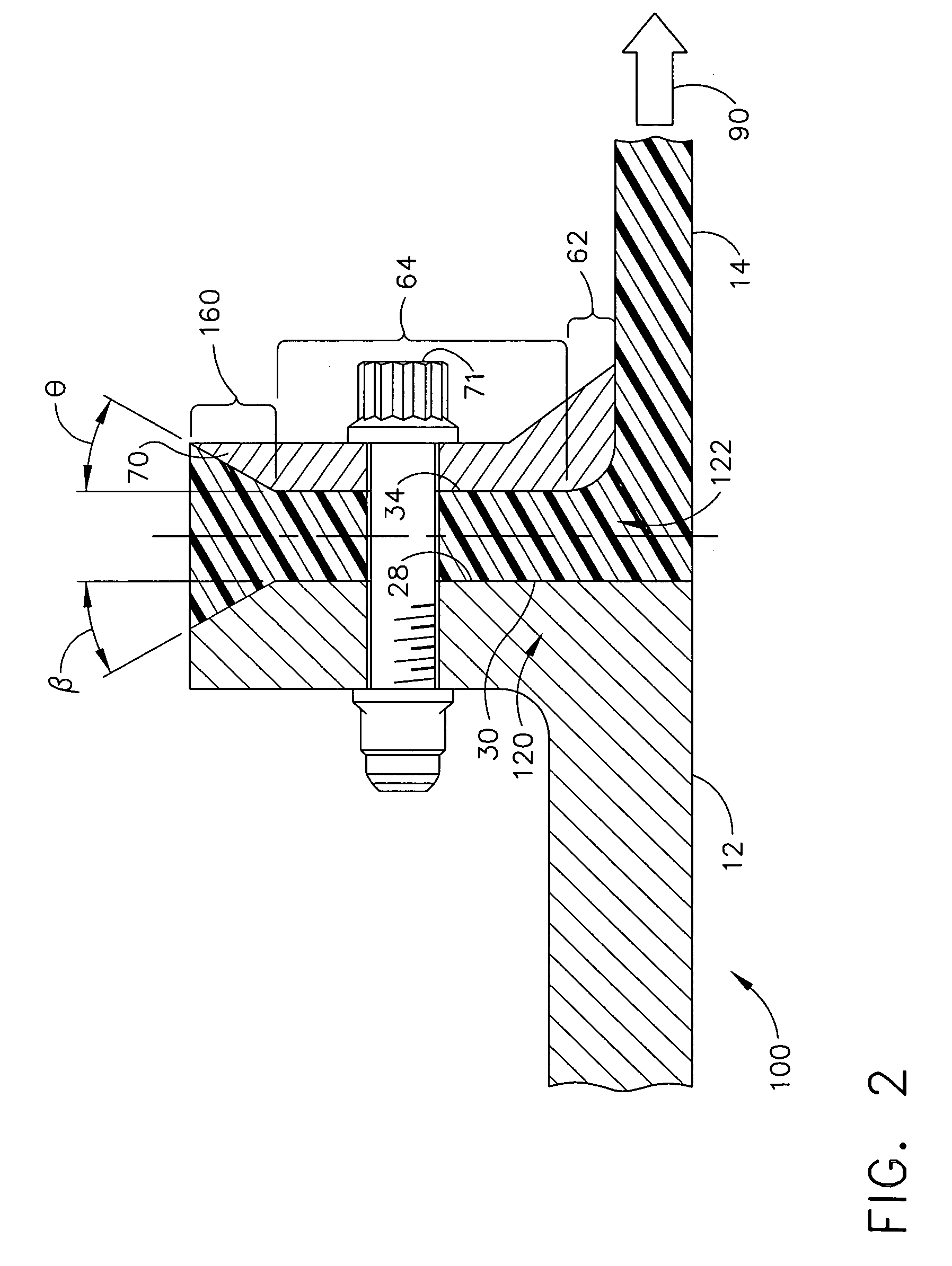
[0012] In the exemplary embodiment, each component 12 and 14 includes a re...


PUM

PropertyMeasurementUnit
Structureaaaaaaaaaa
Shapeaaaaaaaaaa

Abstract

A method facilitates assembling a turbine engine casing. A first casing section is positioned radially outward from a turbine engine. The first casing includes a first flange having an outer end portion, an inner end portion, and a body therebetween. At least a portion of the outer end portion has a partial frusto-conical cross-sectional profile. A second casing section including a second flange is positioned adjacent the first casing section such that a mating surface of the second flange is positioned substantially flush against a first flange mating surface. Each respective mating surface is opposite a respective load-bearing surface. A fastener is inserted through an opening in the first and second flanges to couple casing sections together such that a portion of a load-bearing surface extending over the first flange outer end portion facilitates distributing loading induced therein substantially equally across the load bearing surface.

Description

BACKGROUND OF THE INVENTION [0001] This invention relates generally to composite structures, and more particularly, to methods and apparatus for assembling gas turbine engines. [0002] Gas turbine engine assemblies typically include an engine casing that extends circumferentially around the turbine engine. At least some known engine casings are fabricated from segmented sections that are coupled together generally axially via flanges extending from the adjoining sections of the casing. Specifically adjacent flanges are coupled together via fasteners which are inserted through parallel flanges extending substantially perpendicularly outward from the casing section. During operation of the engine, vibrational loading induced from the engine to the casing may induce vibrational stresses and loading to the flanges. Over time, continued exposure to the vibrational loading may cause the fasteners to loosen, a condition known as fastener pull out, and / or may lead to premature failure of the...

Claims


Application Information

Patent Timeline
IPC IPC(8): F16B5/06F01D25/00B23P15/00
CPCB29C65/562Y10T403/27B29C66/54B29C66/721B29L2031/7504F01D25/243F16L23/032F16L47/14F16L47/24F05D2300/603Y10T403/64Y10T403/648Y10T403/645Y10T29/49236B29C66/1312F16B2200/50F16B2200/506F16B2200/509
Inventor BLANTON, LEE ALAN
Owner GENERAL ELECTRIC CO
Why Eureka
Try Eureka