Electromagnetic relay

Active Publication Date: 2007-04-19
EM DEVICES CORP
View PDF3 Cites 4 Cited by
  • Summary
  • Abstract
  • Description
  • Claims
  • Application Information

AI Technical Summary

Benefits of technology

[0047] In the disclosed electromagnetic relay, since the insert-molding is performed on the group of external connecting terminals, a contact area between each of the external connecting terminals and the electrically insulating material is large and excellent contact between each of the external connecting terminals and the electrically insulating material is obtained and, therefore, heat of the group of the external connecting terminals is easily transferred to the entire base, which enables heat to be dissipated from the entire base and, as a result, the rise in temperatures within the electromagnetic relay is suppressed. Moreover, the group of the external connecting terminals and fixed contacts are formed from at least one piece of a plate-shaped conductive material by a cutting and bending process, which achieves the ease of handling materials and members.
[0048] However, in the electromagnetic relay, since the fixed contacts, as in the case of the external connecting te

Problems solved by technology

However, in the conventional electromagnetic relay that carries a current of several tens of amperes for control of a motor, a solenoid, or a like, a rise in temperatures occurs due to heat generated at a contact making up a current-carrying path, terminal, movable spring, or a like and due to hea

Method used


Image

  • Electromagnetic relay
  • Electromagnetic relay
  • Electromagnetic relay

Examples


first embodiment

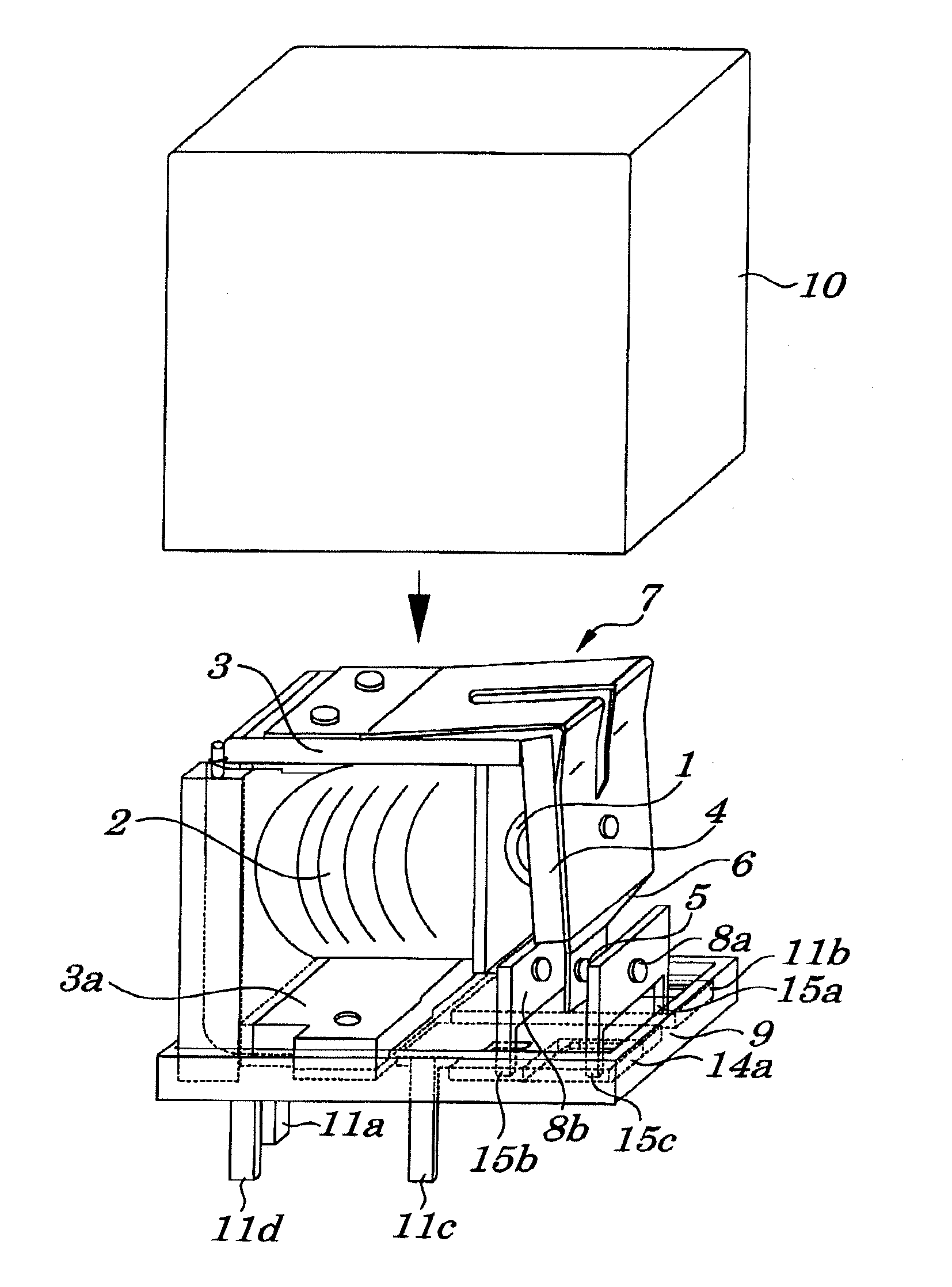
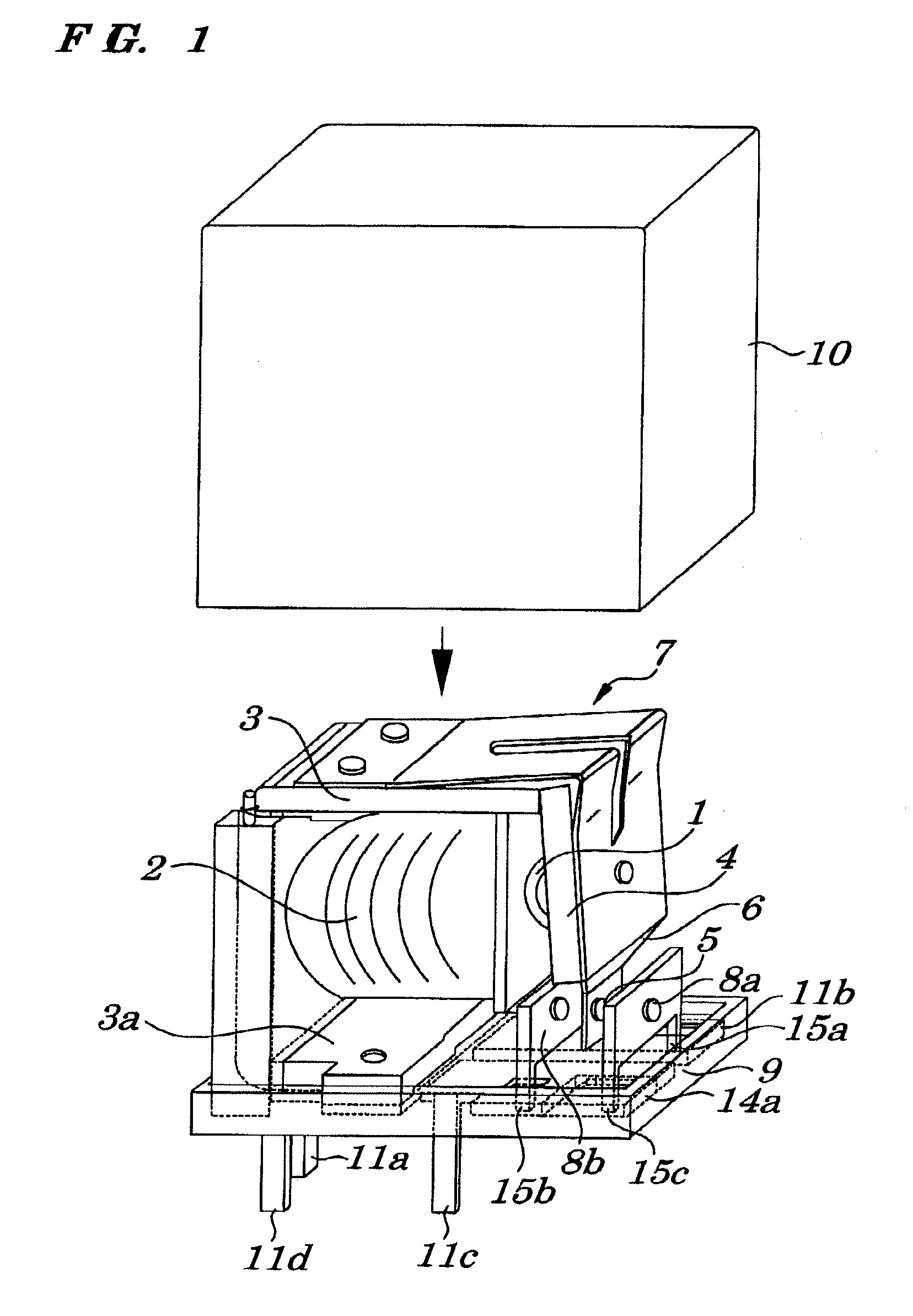
[0055]FIG. 1 is a perspective view of an electromagnetic relay according to a first embodiment of the present invention. As shown in FIG. 1, the electromagnetic relay includes a core 1, a coil 2, a yoke 3, an armature 4, an electromagnetic block 7 made up of a movable spring 6 having a movable contact 5 mechanically coupled to the armature 4, a pair of fixed contacts made up of an ordinarily closed fixed contact 8a and an ordinarily opened fixed contact 8b both being contact with the movable contact 5 in a manner in which both the fixed contacts 8a and 8b strike the movable contact 5 to come into physical contact, a group of external connecting terminals made up of a movable contact external connecting terminal 11a electrically connected to the movable contact 5, an ordinarily closed fixed contact external connecting terminal 11b electrically connected to the ordinarily closed fixed contact 8a, an ordinarily opened fixed contact external connecting terminal 11c electrically connecte...

second embodiment

[0061] The configurations of the electromagnetic relay of the second embodiment differ from those in the first embodiment only in the method of fabricating securing bodies 14a and 14b.

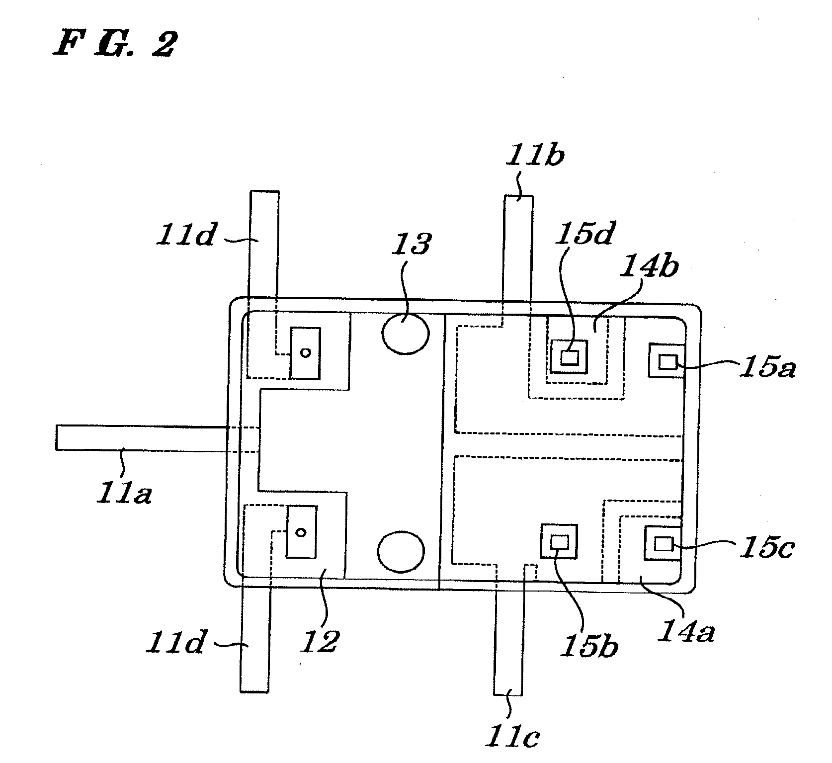
[0062]FIG. 3 is a plan view showing configurations of a base and a group of external connecting terminals to be used in the second embodiment. As in the case of FIG. 2, FIG. 3 shows a state in which each external connecting terminal and each securing body are cut and separated from one piece of a metal plate.

[0063] However, as shown in FIG. 3, the securing bodies 14a and 14b and the ordinarily opened fixed contact external connecting terminal 11c and ordinarily closed fixed contact external connecting terminal 11b are molded by a press in a state in which each of the securing bodies 14a and 14b is partially coupled to each of the external connecting terminals 11c and 11b and then the insert-molding is carried out. Each of coupling portions 16 is exposed from an upper surface of a base 9 and is remove...


PUM


Abstract

An electromagnetic relay is provided which allows free design of arrangements of each external connecting terminal and is capable of effectively dissipating heat from a base and suppressing a rise in temperatures within the electromagnetic relay. The electro-magnetic relay includes a core, a coil, a yoke, an armature, an electromagnetic block made up of a movable spring having a movable contact mechanically coupled to the armature, a pair of fixed contacts made up of an ordinarily closed fixed contact and an ordinarily opened fixed contact both being contacted with the movable contact, a group of external connecting terminals, a base, and an armored cover, wherein the movable spring and the yoke make up part of a current-carrying path, and a yoke extended portion is in direct mechanical contact with the movable contact external connecting terminal and the ordinarily closed fixed contact is mechanically coupled to an ordinarily closed fixed contact external connecting terminal.

Description

BACKGROUND OF THE INVENTION [0001] 1. Field of the Invention [0002] The present invention relates to an electromagnetic relay to be mounted on a printed circuit board or a like and more particularly to the electromagnetic relay to control the switching ON / OFF of a current as comparatively large as about several tens of amperes used in automotive electrical devices, household electrical appliances, or a like. [0003] The present application claims priority of Japanese Patent Application No. 2005-292381 filed on Oct. 5, 2005, which is hereby incorporated by reference. [0004] 2. Description of the Related Art [0005] An example of a conventional electromagnetic relay to switch conduction for control of a motor, a solenoid, or a like is disclosed in Patent Reference 1 (Japanese Utility Model Application No. Hei 03-86545) which includes an electromagnet made up of a coil, a core, and a yoke, an armature which is attracted by the electromagnet, a movable contact spring to make the armature ...

Claims


Application Information

Patent Timeline
IPC IPC(8): H05K1/00
CPCH01H50/04H01H50/14H01H50/60H01H51/04H01H2050/362
Inventor OTA, YOSHINORIIDE, TATSUMI
Owner EM DEVICES CORP
Why Eureka
Try Eureka