Heatsink for concentrating or focusing optical/electrical energy conversion systems

a technology of optical/electrical energy conversion and heat sink, which is applied in the direction of generator/motor, light radiation electric generator, pv power plant, etc., can solve the problems of increasing the operating temperature of the device, affecting device performance, stability, and longevity,

Inactive Publication Date: 2007-04-26
SOLIANT ENERGY INC
View PDF70 Cites 62 Cited by
  • Summary
  • Abstract
  • Description
  • Claims
  • Application Information

AI Technical Summary

Benefits of technology

[0026] In preferred embodiments, one or more of the fin(s) extend toward and attach to the optical element. Advantageously, attaching a fin to the optical element can help register and suspend the heatsink including the fin above the optical element.

Problems solved by technology

In most cases, devices used at the focus of optical focusing elements have inefficiencies that result in the generation of thermal energy.
This thermal energy may increase the device operating temperature and, as a result, may affect device performance, stability, and longevity.
When these systems use dish reflectors to concentrate sunlight onto photovoltaic solar cells, the concentrated sunlight typically results in high power per unit area on the solar cell.

Method used


Image

  • Heatsink for concentrating or focusing optical/electrical energy conversion systems
  • Heatsink for concentrating or focusing optical/electrical energy conversion systems
  • Heatsink for concentrating or focusing optical/electrical energy conversion systems

Examples


Embodiment Construction

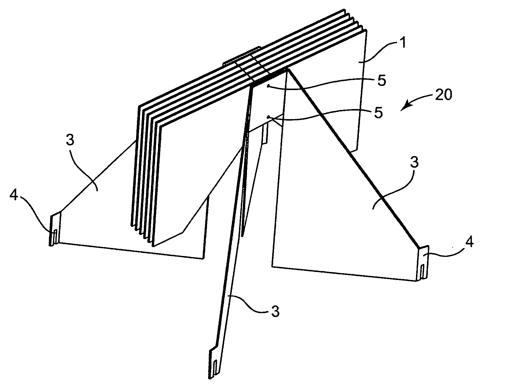
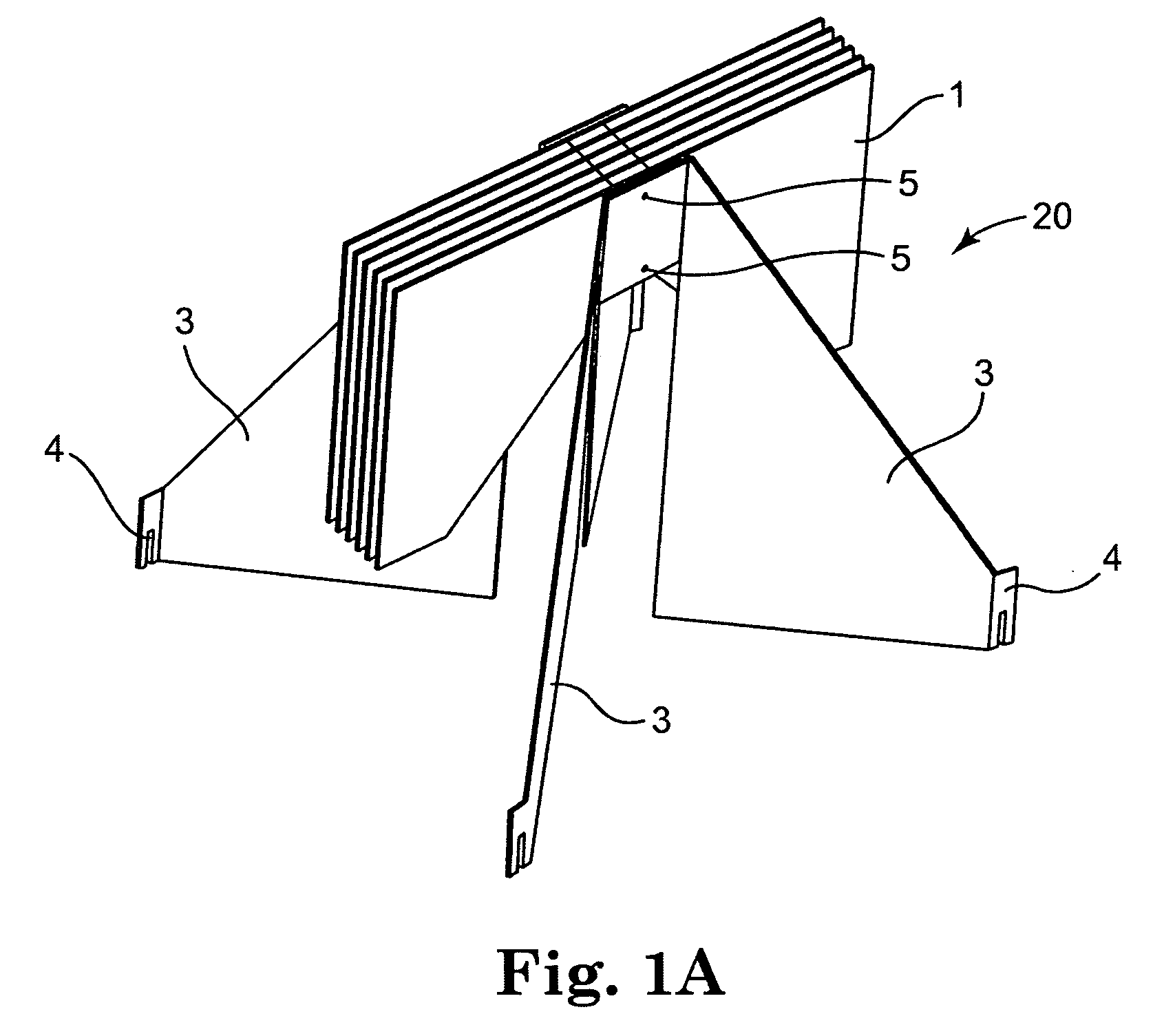
[0041] For purposes of illustration a heatsink according to the present invention is described below in the context of being applied to concentrating or focusing optical / electrical energy conversion systems. As used herein, the term “focusing” includes imaging focusing and / or non-imaging focusing. The heat sinks are preferably applied to the optical focusing elements such as those used in concentrating systems.

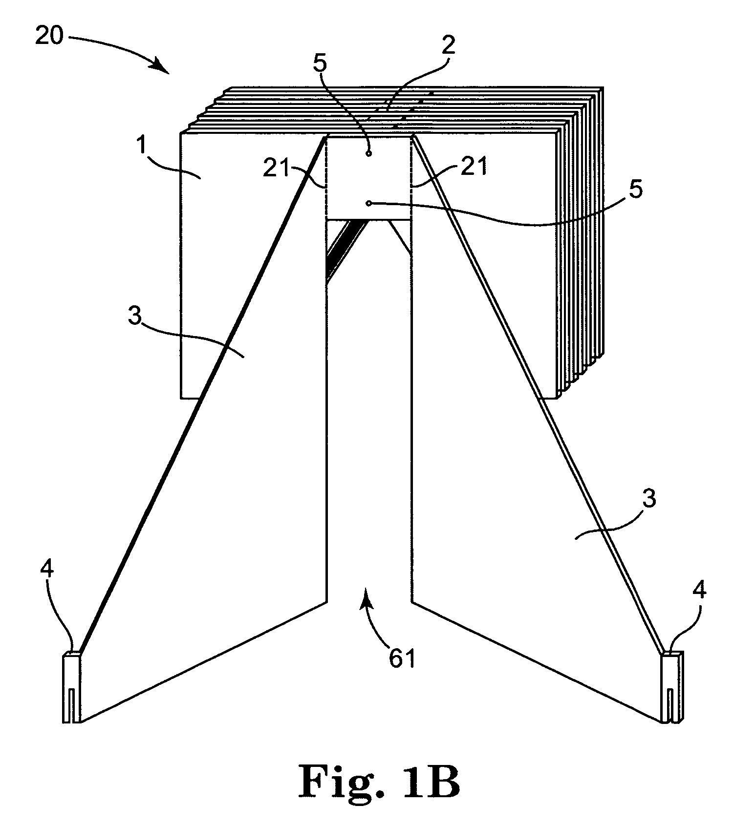
[0042]FIGS. 1A-1G show one preferred embodiment of a heatsink 20 that can be used in a photovoltaic concentrator module 26. Heat sink 20 incorporates respective thermally conductive fins 1 and 3.

[0043] Preferably, heat sink 20 includes at least one, but more preferably two or more parallel, spaced apart fins 1 that are arranged in a stack and are separated by and attached to spacers 2. As shown in FIG. 1G, at least one of the fins 1 may extend radially outward directly from the optical axis 24, while the other fins 1 are parallel to such one fin 1 yet are slightly offset fro...


PUM


Abstract

The present invention relates to heatsink technology for helping to dissipate thermal energy generated or absorbed with respect to optical focusing and/or concentrating systems such as projectors and spotlights as well as trough or dish reflectors. More specifically, the present invention relates to heat sink technology for helping to dissipate thermal energy generated by or absorbed in the proximity of the focus of optical concentrating elements of solar concentrator modules, wherein the heat sink includes a plurality of heat dissipating fins.

Description

PRIORITY CLAIM [0001] The present non-provisional patent Application claims priority under 35 USC §119(e) from United States Provisional Patent Application having Ser. No. 60 / 723,336, filed on Oct. 4, 2005, and titled A HEATSINK FOR CONCENTRATING OR FOCUSING OPTICAL / ELECTRICAL ENERGY CONVERSION SYSTEMS, wherein the entirety of said provisional patent application is incorporated herein by reference.FIELD OF THE INVENTION [0002] The present invention relates to heatsink technology for helping to dissipate thermal energy generated or absorbed with respect to optical focusing and / or concentrating systems such as projectors and spotlights as well as trough or dish reflectors. BACKGROUND OF THE INVENTION [0003] In general concentrating and projection systems focus light onto, or broadcast light from, a device located in the proximity of the focus of a reflector. Dish and trough reflectors are examples of optical focusing elements. Dish reflectors differ from trough reflectors in that ther...

Claims


Application Information

Patent Timeline
Patent Type & Authority Applications(United States)
IPC IPC(8): H02N6/00
CPCH01L31/052H01L31/0547Y02E10/52
Inventor JOHNSON, RICHARD L. JR.HOLMES, HOWARD C.NEFF, RUSSELL E.
Owner SOLIANT ENERGY INC
Why Eureka
Try Eureka