Anti-vibration tube support for tube bundles having U-shaped bends

a tube bundle and anti-vibration technology, which is applied in the direction of machine supports, safety devices for heat exchange apparatuses, lighting and heating apparatus, etc., can solve the problems of insufficient clearance and the inability to fully insert the support device into the bundle, so as to reduce vibration and reduce the effect of reducing and/or eliminating any vibration

Active Publication Date: 2007-04-26
EXXON RES & ENG CO
View PDF23 Cites 18 Cited by
  • Summary
  • Abstract
  • Description
  • Claims
  • Application Information

AI Technical Summary

Benefits of technology

[0016] Another aspect of the present invention is to provide a method of reducing vibration in a heat exchanger or other device having a tube bundle. At least one tube support device is located within the space between adjacent rows of elongated tubes near the U-shaped bend portion of the tubes. The tube support dev

Problems solved by technology

There may be instances where insufficient clearance exists between the tubes such that th

Method used


Image

  • Anti-vibration tube support for tube bundles having U-shaped bends
  • Anti-vibration tube support for tube bundles having U-shaped bends
  • Anti-vibration tube support for tube bundles having U-shaped bends

Examples


Embodiment Construction

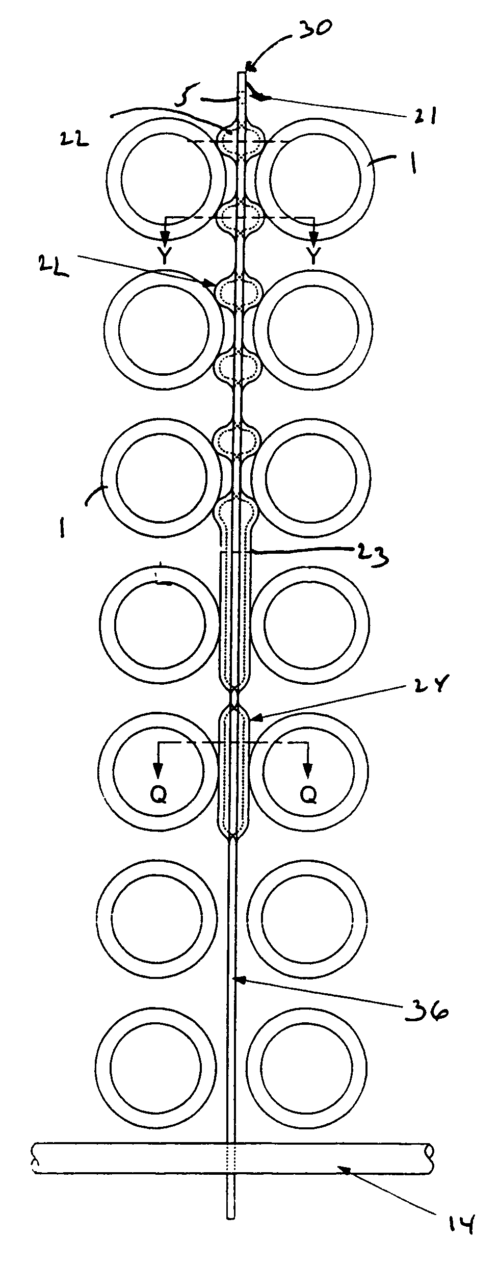
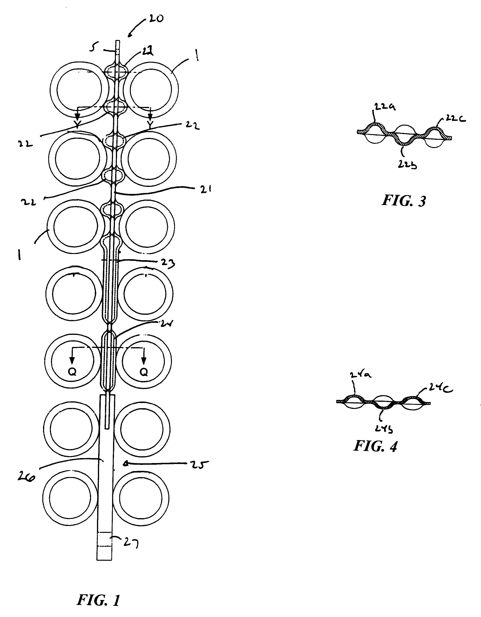
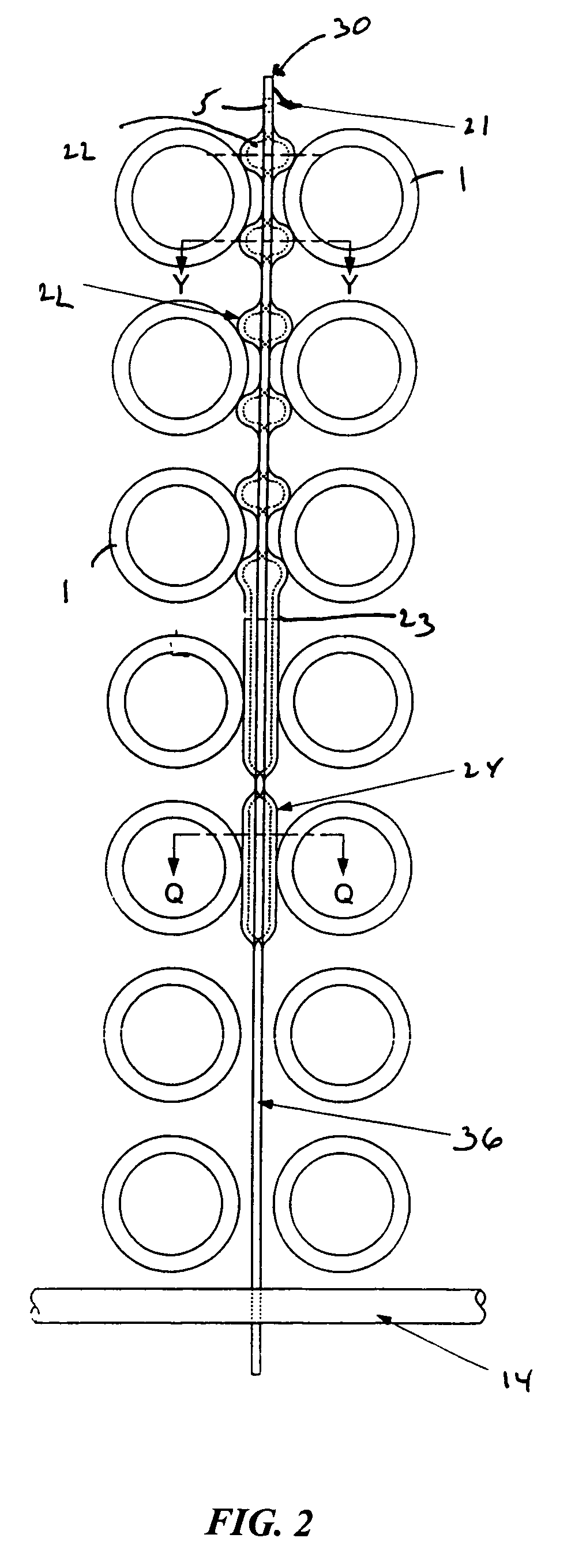
[0033] The heat exchanger includes an array of elongated tubes or rods 1 arranged in a bundle. As shown in FIGS. 14 and 15, each tube or rod 1 preferably includes a first elongated linear section 11 that extends along one side of the bundle. A second elongated linear section 12 extends along an opposite side of the bundle. A U-shaped bend portion13 interconnects sections 11 and 12. The tubes 1 may be arranged in a rectangular configuration, as shown in FIGS. 1, 2 and 11 or a triangular configuration, as shown in FIG. 13. An anchor assembly 14 extends through the bundle adjacent the U-shaped bend portion 13, as shown in FIGS. 14 and 15. The inner tubes 1 (i.e., those tubes or rods that are located closest to the anchor assembly 14) are generally much stiffer than the tubes 1 that are located near the exterior of the bundle. The outer tubes are more susceptible to vibration and chatter. The anchor assembly 14 is inserted into the bundle prior to insert of the tube support devices, des...


PUM


Abstract

A tube support device for a tube bundle having a plurality of elongated tubes with a U-shaped bend portion is disclosed. The tube support device includes an elongated longitudinally extending strip having a pair of opposing faces. A plurality of tube engaging members extend from the pair of opposing faces. The tube support device includes an engagement assembly formed on one end of the tube support device. The engagement assembly is adapted to engage the anchor assembly positioned within the tube bundle, whereby the tube support device can be rotated into the desired orientation between the tubes to prevent vibration damage.

Description

CROSS REFERENCE TO RELATED APPLICATIONS [0001] This application relates to and claims priority to U.S. Provisional Patent Application No. 60 / 728,327 to Wanni et al., filed on Oct. 20, 2005 and entitled “Anti-Vibration Tube Support for Tube Bundles having U-shaped Bends.” The disclosure is incorporated herein specifically by reference.FIELD OF THE INVENTION [0002] This invention relates to tube supports devices, commonly referred to as tube stakes. The tube support devices are installed to control flow-induced vibration and prevent movement of the tubes or rods within a tube bundle. Specifically, the present invention relates to a tube support device to be installed in the portion of the tube bundle wherein the elongated tubes have U-bends whereby the flow direction within the tubes is reversed. The present invention is useful with tube or rod bundles in heat exchangers, steam generators and similar fluid-handling equipment. It is contemplated that the present invention may be used i...

Claims


Application Information

Patent Timeline
IPC IPC(8): F28F7/00
CPCF22B37/205F22B37/206F28D7/06F28F9/0132F28F2265/30F28F9/013F28F9/007
Inventor WANNI, AMAR S.RUDY, THOMAS M.
Owner EXXON RES & ENG CO
Why Eureka
Try Eureka