Metal-to-metal non-elastomeric seal stack

a non-elastomeric, metal-to-metal technology, applied in sealing/packing, mechanical equipment, borehole/well accessories, etc., can solve the problems of degrading the seal, increasing the pressure and temperature of the seal, and imposing the use limits of sliding sleeve devices at these lower depths, etc., to achieve greater temperature and pressure, greater operational life, and more robust

Active Publication Date: 2007-04-26
BAKER HUGHES INC
View PDF18 Cites 36 Cited by
  • Summary
  • Abstract
  • Description
  • Claims
  • Application Information

AI Technical Summary

Benefits of technology

[0010] In operation, the thermoplastic seal elements of the seal assembly form a dynamic fluid seal against both the outer housing and the inner sleeve member. Also, resilient metal-to-metal contact is provided by the C-seal portions of the seal system against both the outer housing and the sleeve member. The metallic construction of the C-seals provides erosion resistance and protection for the thermoplastic components of the seal system. Additionally, the metallic C

Problems solved by technology

Limitations on the use of sliding sleeve devices at these lower depths are imposed by the increased pressures and temperatures upon the seals.
In applications where there is a high pressure differential between the interior flowbore and the surrounding annulus, opening and closing of the sleeve valve will d

Method used


Image

  • Metal-to-metal non-elastomeric seal stack
  • Metal-to-metal non-elastomeric seal stack
  • Metal-to-metal non-elastomeric seal stack

Examples


Embodiment Construction

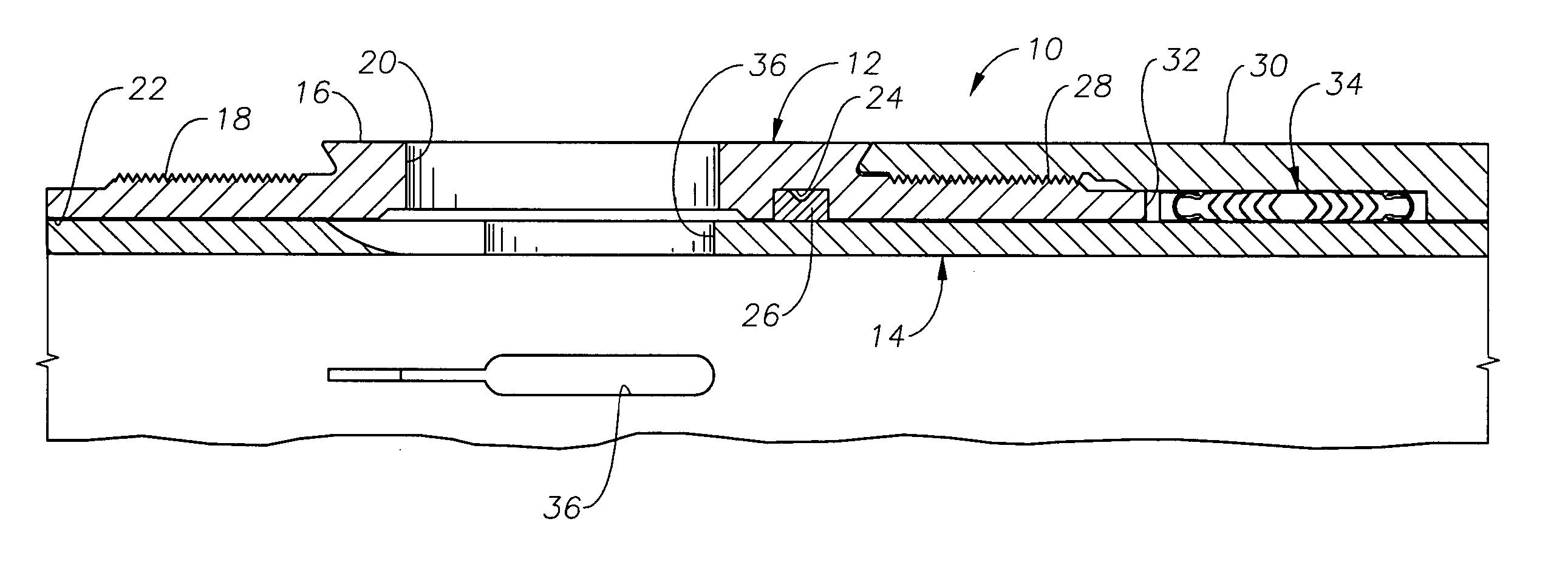
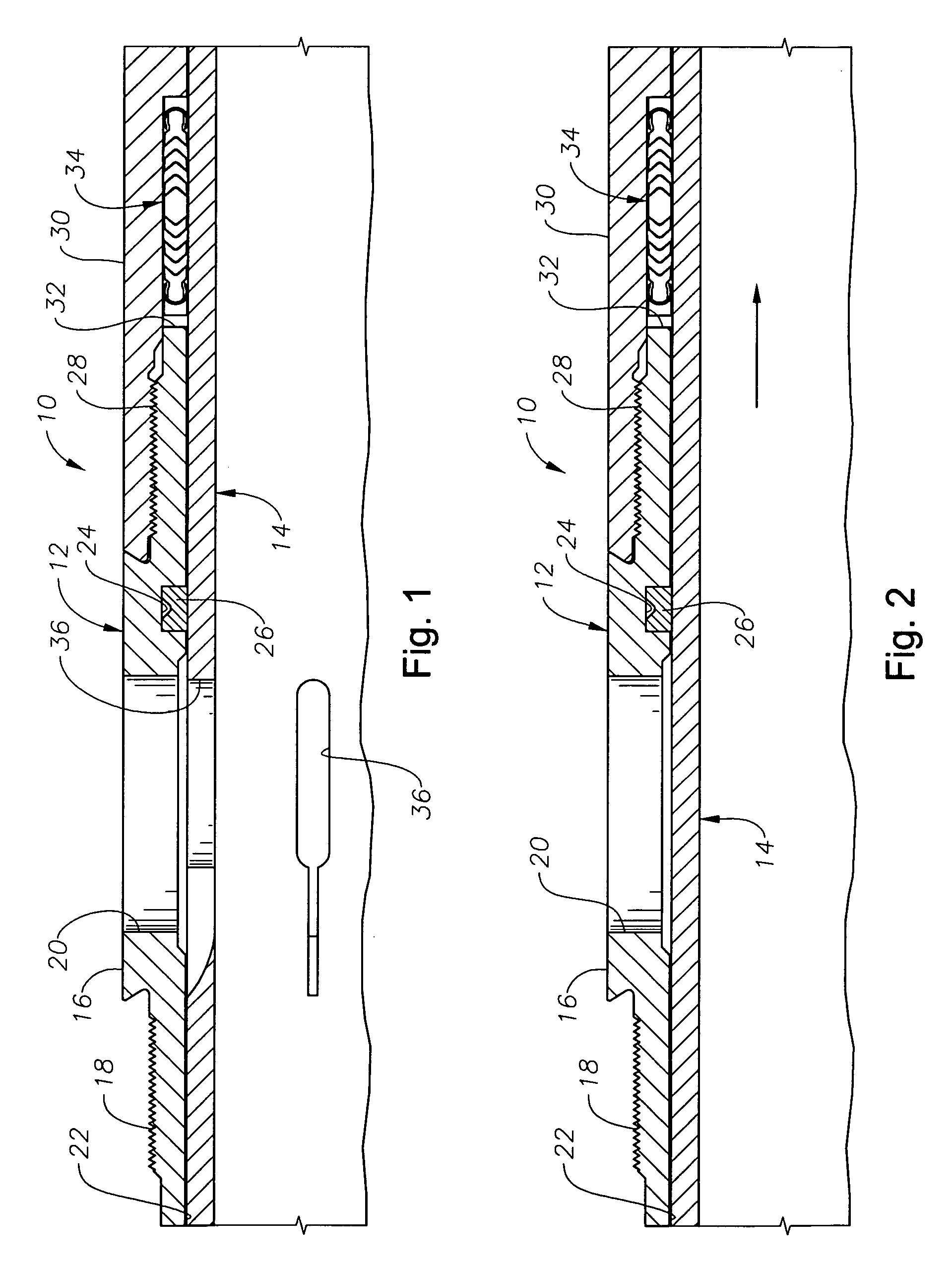
[0017]FIGS. 1 and 2 illustrate an exemplary sliding sleeve valve 10. The sleeve valve 10 includes a tubular outer housing 12 and an inner sleeve member 14 that is axially movable with respect to the outer housing 12 between open, circulating and closed positions, as is known in the art. The outer housing 12 includes an upper sub 16 having a threaded end portion 18 for interconnection with other portions of a production string (not shown) in a manner known in the art. A lateral fluid flow port 20 is disposed through the upper sub 16 to allow fluid communication between the exterior of the upper sub 16 and the axial flowbore 22 that is defined therewithin. Below the flow port 20 is an internal annular recess 24, which retains a diffuser ring 26 therein. The diffuser ring 26 acts to slow fluid flow rate into or out of the valve 10 during opening or closing to help prevent damage to the seal assembly 34. The diffuser ring 26 is preferably of the type described in U.S. Pat. No. 5,156,220...


PUM


Abstract

An improved seal assembly for use in sliding sleeve valves. The seal assembly incorporates a number of annular, chevron-shaped seal elements that are in a stacked configuration and preferably formed of a thermoplastic material to provide a fluid seal between the outer housing and the inner sleeve member of the sliding sleeve valve. In addition, the seal assembly preferably includes a pair of annular metallic seal members that have a C-ring cross-section (a “C-seal”). On opposite axial sides of each metallic C-seal are a C-seal support ring and an end adapter that are shaped and sized to assist the metallic C-seals to be axially compressed and uncompressed to resiliently seal against both the inner sleeve member and the outer housing.

Description

BACKGROUND OF THE INVENTION [0001] 1. Field of the Invention [0002] The invention relates generally to sliding sleeve devices of the type used within a wellbore, and more particularly, the design of seals used within a sliding sleeve device. [0003] 2. Description of the Related Art [0004] Sliding sleeve devices are used to allow selective fluid communication between a flowbore and a surrounding annulus in a wellbore. Typically, there devices are used as valves that are selectively opened and / or closed to accomplish a particular function within the wellbore. One typical use for such valves is to inject chemical inhibitors, stimulants, or the like into the annulus from the flowbore. During the production phase, sliding sleeve valves are often used to control the amount of flow of production fluid from the annulus into the flowbore. Many other uses for these devices are known in the art. [0005] Conventional sliding sleeve devices include an outer housing with at least one lateral fluid...

Claims


Application Information

Patent Timeline
IPC IPC(8): E21B34/00
CPCE21B34/14E21B2033/005E21B2200/01F16J15/20
Inventor GOMEZ, ALFREDO
Owner BAKER HUGHES INC
Why Eureka
Try Eureka