
Low threshold voltage semiconductor device with dual threshold voltage control means

a technology of low threshold voltage and control means, which is applied in the field of semiconductor devices with dual threshold voltage control means, can solve the problems of enhancing short channel effects, performance degradation, and/or shifting the flatband voltage of the device, and achieve the effect of improving threshold voltage and flatband voltage stability

Inactive Publication Date: 2007-04-26
TAIWAN SEMICON MFG CO LTD
View PDF10 Cites 20 Cited by
  • Summary
  • Abstract
  • Description
  • Claims
  • Application Information

AI Technical Summary

Benefits of technology

The present invention solves the problem of threshold and flatband voltage variation in semiconductor devices by using a high k dielectric with a Si or Ge content of greater than 50% and at least one other means for threshold / flatband voltage tuning, such as an insulating interlayer or an engineered device channel. The high k gate dielectric and the at least one element stabilize the gate stack's threshold / flatband voltage to a targeted value. The method includes providing a structure on a semiconductor substrate with a gate stack comprising a high k gate dielectric and a Si- or Ge-containing gate conductor, and at least one element, and applying a bias to the gate stack. The technical effect of the invention is to improve the stability of the semiconductor device's threshold voltage and flatband voltage.

Problems solved by technology

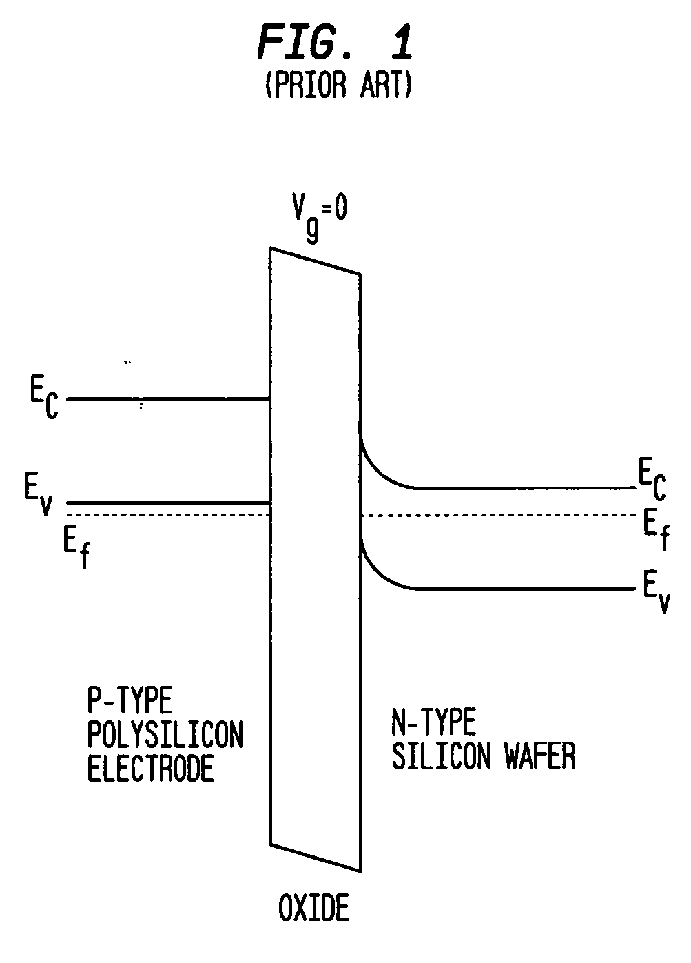
Unfortunately, when p-type field effect transistors are fabricated using a dielectric such as hafnium oxide or hafnium silicate, it is a well known problem that the flatband voltage of the device is shifted from its ideal position of close to about +1 V, to about 0+ / −300 mV.
Although substrate engineering is one possible means to stabilize threshold voltage shift, it can do so to a limited extent, which is inadequate for FETs, particularly pFETs, that include a gate stack comprising a poly-Si gate electrode and a hafium-containing high dielectric constant gate dielectric.
Implant channel engineering can also move the threshold voltage, but may cause performance degradation and / or enhanced short channel effects.

Method used


Image

  • Low threshold voltage semiconductor device with dual threshold voltage control means
  • Low threshold voltage semiconductor device with dual threshold voltage control means
  • Low threshold voltage semiconductor device with dual threshold voltage control means

Examples


Embodiment Construction

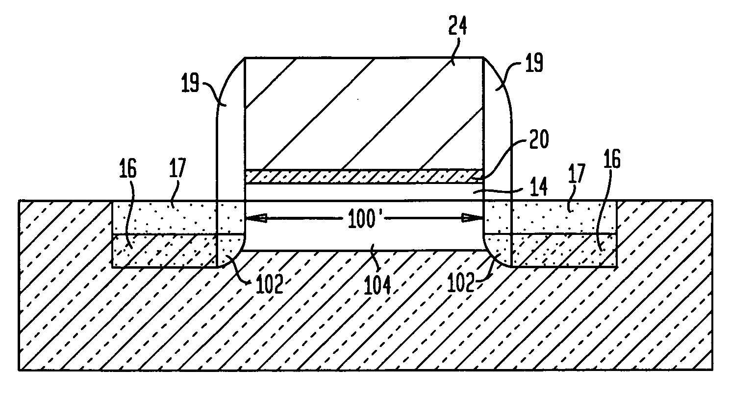
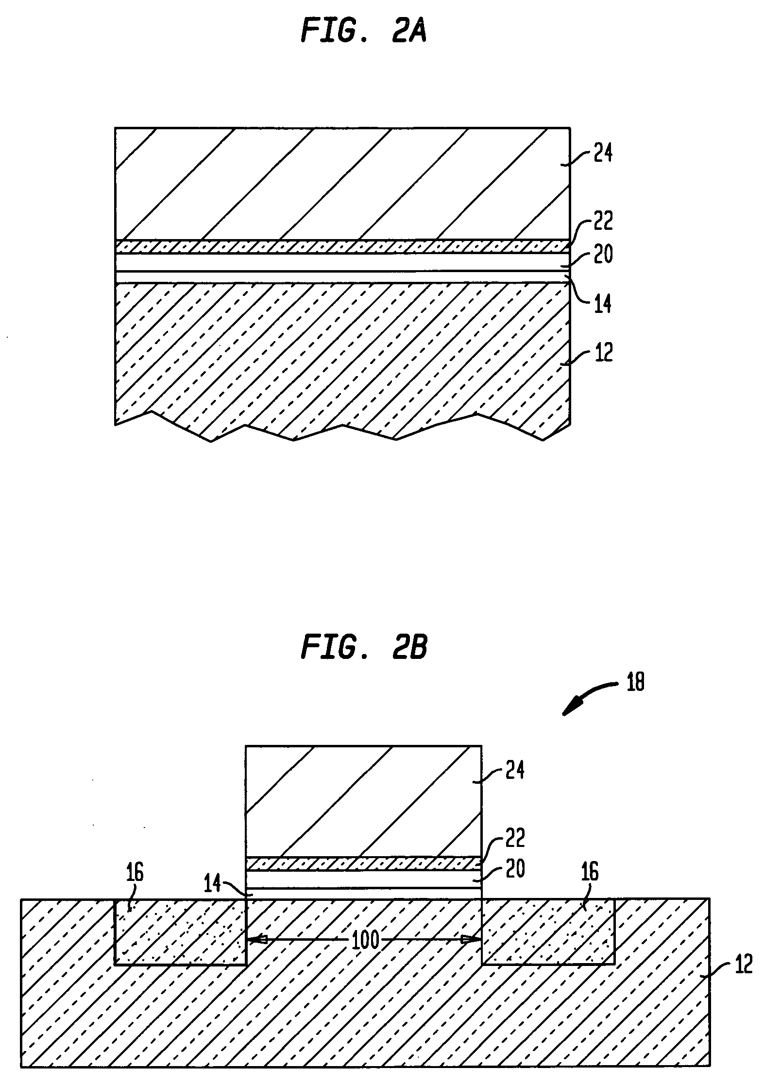
[0025] The present invention, which provides a semiconductor structure, such as a FET, with low threshold voltage and flatband shifts as well as a method of fabricating the same, will now be described in greater detail in the discussion that follows. It is noted that in the following discussion reference will be made to certain drawings that are provided for illustrative purposes. Since the drawings are provided for illustrative purposes, they are not drawn to scale.

[0026] It is emphasized that the present invention provides threshold voltage control for semiconductor devices, especially pFETs, by utilizing a dielectric having a high k dielectric and a high content of Si or Ge (greater than 50%) and at least one other means for tuning the threshold voltage such as, for example, incorporating an insulating interlayer between the dielectric and the overlying conductor or by channel engineering (i.e., counterdoping and / or halo doping tuning). In the following description, a FET is des...


PUM


Abstract

A semiconductor structure, particularly a pFET, which includes a dielectric material that has a dielectric constant of greater than that of SiO2 and a Ge or Si content of greater than 50% and at least one other means for threshold / flatband voltage tuning by material stack engineering is provided. The other means contemplated in the present invention include, for example, utilizing an insulating interlayer atop the dielectric for charge fixing and / or by forming an engineered channel region. The present invention also relates to a method of fabricating such a CMOS structure.

Description

FIELD OF THE INVENTION [0001] The present invention relates to a semiconductor structure, and more particularly to a complementary metal oxide semiconductor (CMOS) structure, particularly a pFET, which includes a dielectric material that has a dielectric constant of greater than that of SiO2 and a Ge or Si content of greater than 50% and at least one other means for threshold / flatband voltage tuning by material stack engineering. The other means contemplated in the present invention include, for example, utilizing an insulating interlayer atop the dielectric for charge fixing and / or by forming an engineered channel region. The present invention also relates to a method of fabricating such a semiconductor structure. BACKGROUND OF THE INVENTION [0002] In standard silicon complementary metal oxide semiconductor (CMOS) technology, p-type field effect transistors (pFET) use a boron (or other acceptor) doped p-type polysilicon layer as a gate electrode that is deposited on top of a silico...

Claims


Application Information

Patent Timeline
Patent Type & Authority Applications(United States)
IPC IPC(8): H01L29/94H01L21/8238
CPCH01L21/28194H01L21/28238H01L21/823807H01L29/105H01L29/1083H01L29/513H01L29/517H01L29/518H01L29/6659H01L29/7833H01L21/823857
Inventor CARTIER, EDUARD A.COPEL, MATHEW W.FRANK, MARTIN M.GOUSEV, EVGENI P.JAMISON, PAUL C.JAMMY, RAJARAOLINDER, BARRY P.NARAYANAN, VIJAY
Owner TAIWAN SEMICON MFG CO LTD
Learn More