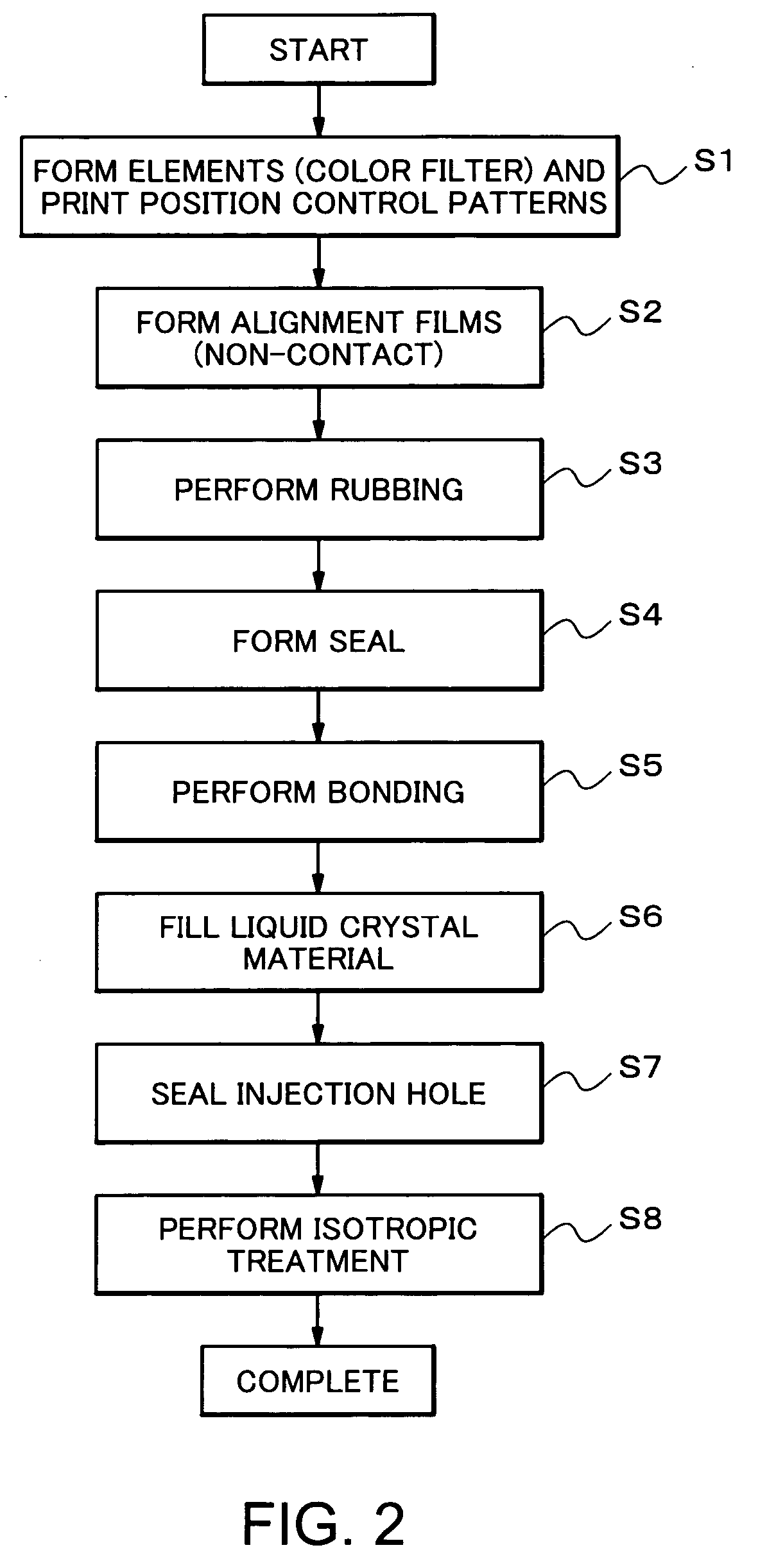
Liquid crystal display device and method of manufacturing the same
- Summary
- Abstract
- Description
- Claims
- Application Information
AI Technical Summary
Benefits of technology
Problems solved by technology
Method used
Image

Examples
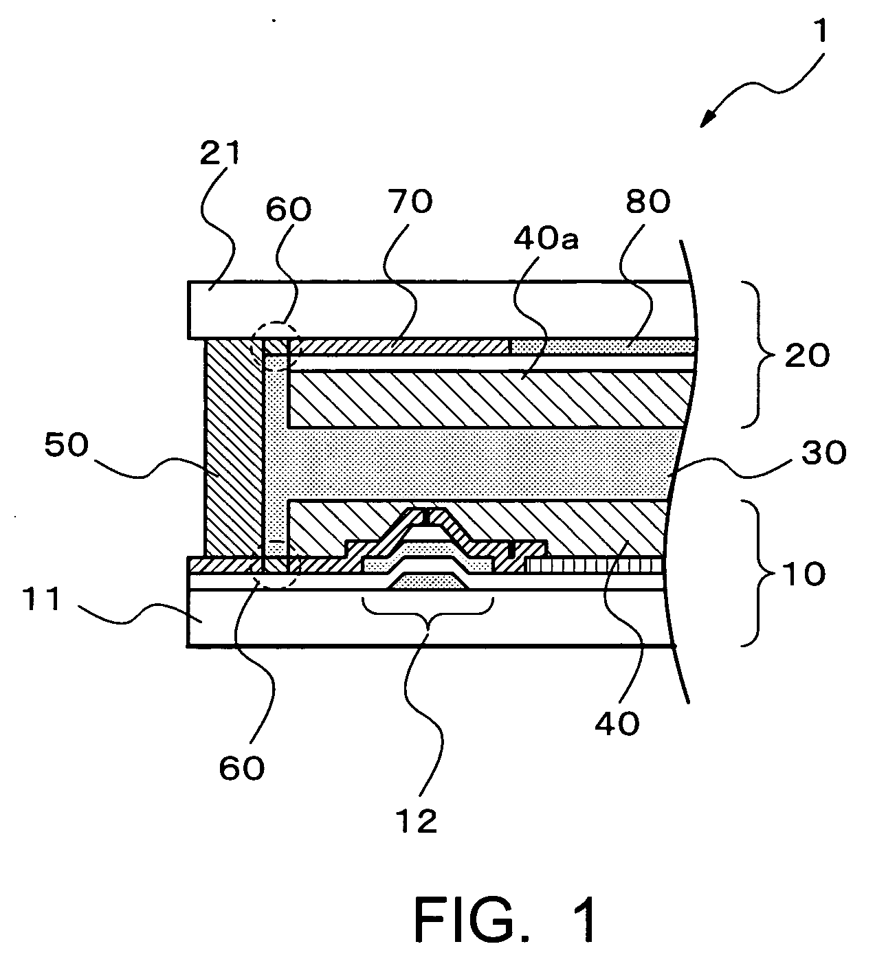
first embodiment
(First Embodiment)
[0077] In the first embodiment of the invention, each of print position control patterns 60 is formed as a region which can easily repel the alignment film material, i.e., a region to which a low surface energy treatment is performed and which has high water repellency to the alignment film material.
[0078] Referring to FIG. 4, an alignment film printing apparatus for printing the alignment films of this embodiment is described. An alignment film printing apparatus 410 includes a tank 413 for storing an alignment film material 411, a print head 414 for discharging the alignment film material 411 onto a substrate 11, and a stage 416 on which the substrate 11 is placed. The print head 414 is filled with the alignment film material 411 through a supply tube from the tank 413 of the alignment film material 411. In the print head 414, nozzles for discharging the alignment film material 411 at equal intervals are arranged, and each of the nozzles has a mechanism for arbi...
second embodiment
(Second Embodiment)
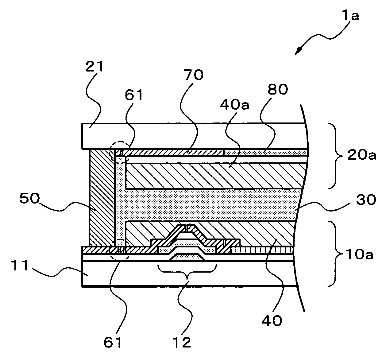
[0085] This embodiment is characterized by forming, between a sealing member 50 and each of display regions on the respective substrates, the print position control patterns consisting of a concave structures or convex structures 61 capable of repelling the alignment film material which forms alignment films 40 and 40a.
[0086] This LCD device 1a includes an array substrate 10a as a first substrate, a color filter substrate 20a as a second substrate, the sealing member 50 joining the first and second substrates, and a liquid crystal layer 30 interposed between the first and second substrates. The alignment films 40 and 40a are provided on the surfaces of the respective substrates, the surfaces being in contact with the liquid crystal layer 30.
[0087] As for the print position control patterns of this embodiment, at least the concave structures or the convex structures 61 are formed by a photolithographic method. Moreover, the alignment films 40 and 40a are deposite...
third embodiment
(Third Embodiment)
[0100] Next, a third embodiment as a specific embodiment of the invention is described with reference to FIG. 14. This embodiment is characterized by forming, between a sealing member 50 and each of display regions on the respective substrates, pillar-shaped bodies 62 and 62a each made of a pillar-shaped member as print position control patterns on the respective substrates, the print position control patterns being capable of repelling the alignment film material which forms alignment films 40 and 40a. The pillar-shaped bodies 62 and 62a are provided opposed to each other as to support the first and second substrates at a selected space. The pillar-shaped bodies 62 and 62a control the range which the alignment films spread as liquid by enclosing the peripheries of the alignment films 40 and 40a, and thereby making it possible to control the positions where the alignment films 40 and 40a are formed.
[0101] An LCD device 1b of this embodiment includes an array subst...
PUM
 Abstract
Description
Claims
Application Information
 - Generate Ideas
- Intellectual Property
- Life Sciences
- Materials
- Tech Scout
- Unparalleled Data Quality
- Higher Quality Content
- 60% Fewer Hallucinations
Browse by: Latest US Patents, China's latest patents, Technical Efficacy Thesaurus, Application Domain, Technology Topic, Popular Technical Reports.
© 2025 PatSnap. All rights reserved.Legal|Privacy policy|Modern Slavery Act Transparency Statement|Sitemap|About US| Contact US: help@patsnap.com