Radio communication method and system, and receiver apparatus and transmitter apparatus

a radio communication system and receiver technology, applied in the field of radio communication systems, radio communication methods, receiver apparatuses and transmitter apparatuses, can solve the problems of significant degradation of demodulation characteristics, errors in demodulated data, and inability to perform signal separation well, so as to achieve sufficient characteristics improvement in retransmission combination, effective functioning of mimo signal separation

Inactive Publication Date: 2007-04-26
FUJITSU LTD
View PDF14 Cites 37 Cited by
  • Summary
  • Abstract
  • Description
  • Claims
  • Application Information

AI Technical Summary

Benefits of technology

[0046] With the foregoing problems in view, one object of the present invention is to realize effective functioning of MIMO signal separation in MIMO transmission, in which two or more antennas are used on the transmitter and receiver ends, even when correlation between transmitter antennas and receiver antennas is high. Further, another object of the invention is to make it possible to realize sufficient characteristics improvement in retransmission combination.
[0059] (1) In comparison with the previous case in which retransmission combination is performed after signal separation, signal separation and reproduction processing is more effectively carried out even when antenna correlation is high, so that sufficient characteristics improvement is realized. Accordingly, it becomes possible to improve the efficiency of retransmission control, thereby improving throughput in data communication.
[0060] (2) Even when retransmission control is not carried out, similar effects to those which are described above are realized by using carriers whose frequencies are separate from one another in the frequency direction, the carriers revealing low correlation thereamong, or by using multiple symbols which are separate from one another in the time direction, the symbols revealing low correlation thereamong.

Problems solved by technology

As a result, by increasing the diffusion rate of a transmission system whose circuit quality (propagation path environment) is poor, it becomes possible to improve the circuit quality.
For example, in a line-of-sight transmission environment, correlation among antennas is high, so that signal separation cannot be well performed by the previous MIMO signal separation method, and errors occur in demodulated data.
In these cases, even if the transmission signal vector is reproduced by the above formula (5), demodulation characteristics are significantly deteriorated due to interference between data streams.
Under such an environment, the previous retransmission combination processing cannot improve the transmission error rate.
However, when correlation among antennas is high, retransmission combination cannot eliminate interference between data streams caused when X (t1) and X (t2) are demodulated (MIMO signal separation), so that demodulation characteristics after retransmission combination are difficult to improve.
It is difficult to control the optimum weight.
Under a condition where the correlation among antennas is high, such as line-of-sight propagation environment, sufficient effect in lowering the correlation among antennas cannot be obtained.
Thus, when antenna correlation is high, interference between data streams in MIMO signal separation remains.

Method used


Image

  • Radio communication method and system, and receiver apparatus and transmitter apparatus
  • Radio communication method and system, and receiver apparatus and transmitter apparatus
  • Radio communication method and system, and receiver apparatus and transmitter apparatus

Examples


first embodiment

[A] First Embodiment

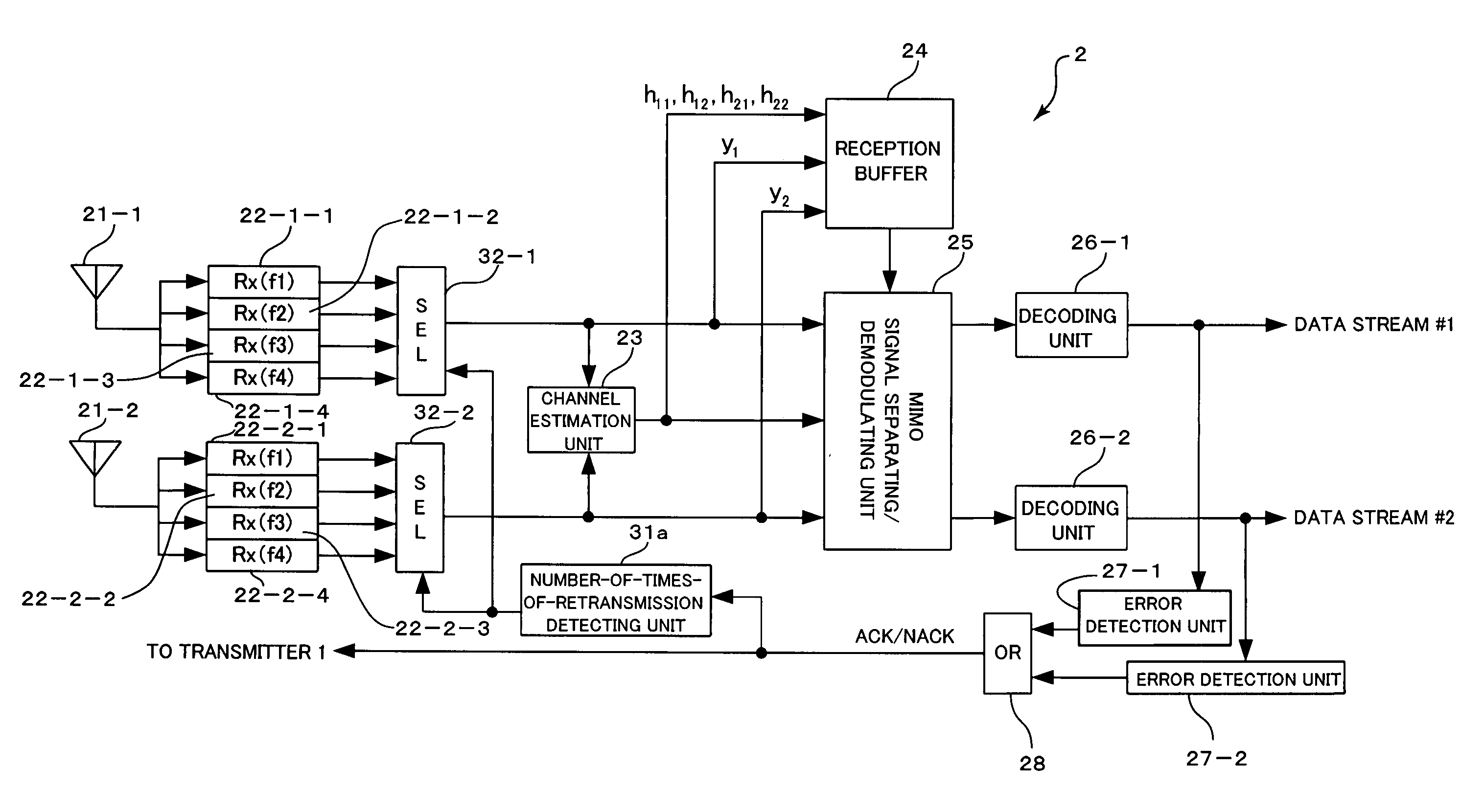
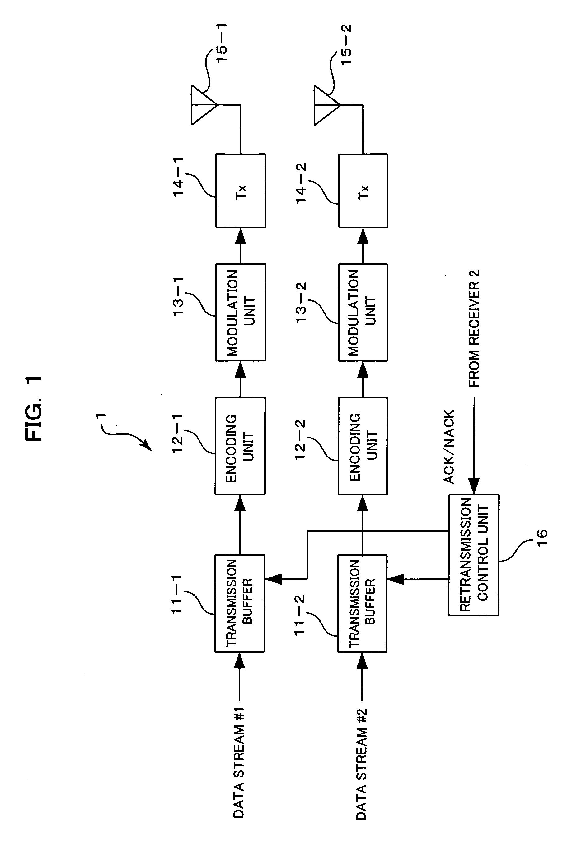
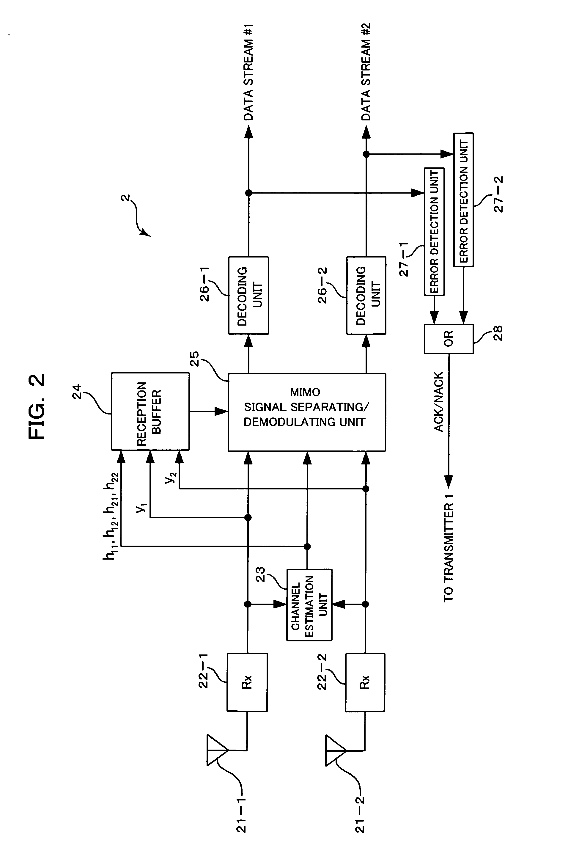
[0080]FIG. 1 and FIG. 2 are block diagrams showing constructions of a MIMO transmitter and a MIMO receiver, respectively, constituting a MIMO communication system according to a first preferred embodiment of the present invention. The MIMO transmitter (transmitter apparatus) 1 of FIG. 1 is similar to the previous MIMO transmitter 100, which has already been described referring to FIG. 16. The MIMO transmitter 1 includes: two antennas 15-1 and 15-2; transmission buffers 11-1 and 11-2, encoding units 12-1 and 12-2, modulation units 13-1 and 13-2, and radio transmission units (Tx) 14-1 and 14-2, provided, one for each of the two transmitter antennas 15-1 and 15-2; and a retransmission control unit 16. The MIMO receiver (receiver apparatus) 2 of FIG. 2 includes: two receiver antennas 21-1 and 21-2; radio receiver units (Rx) 22-1 and 22-2, decoding units 26-1 and 26-2, and error detecting units 27-1 and 27-2, provided, one for each of the two receiver antennas 21-1 an...

second embodiment

[B] Second Embodiment

[0102]FIG. 4 and FIG. 5 are block diagrams showing constructions of a MIMO transmitter and a MIMO receiver, respectively, constituting a MIMO communication system according to a second preferred embodiment of the present invention. The construction shown in FIG. 1 differs from the transmitter 1 of FIG. 4 in that encoding units 12′-1 and 12′-2 in are provided in place of the encoding unit 12-1 and 12-2. The receiver 2 of FIG. 5 differs from the construction shown in FIG. 2 in that reception buffers 29-1 and 29-2 and combining units 30-1 and 30-2, one for each of the receiver antenna 21-i, are added between the MIMO signal separating and modulating unit 25 and the decoding unit 26-i, and that a number-of-times-of-retransmission detecting unit 31 is also added. In FIG. 4 and FIG. 5, the constituent elements which are given the reference characters already described are the same as or similar to the already described constituent elements unless otherwise described. ...

third embodiment

[C] Third Embodiment

[0120] Next, in the third and the fourth embodiment, a method for changing transmitter antennas at retransmission and a method for changing frequencies (carrier frequencies) at the time of retransmission are suggested in order to cope with characteristics deterioration when the fading correlation of the retransmission signal is high, such as in a case where retransmission interval is short in comparison with fading variation. With this method, even when correlation at the time of retransmission does not become low only with fading variation, correlation of the retransmission signal can be decreased, so that sufficient diversity gain can be obtained in combination before MIMO signal separation.

[0121]FIG. 7 is a block diagram showing a construction of a MIMO transmitter constituting a MIMO communication system according to a third preferred embodiment of the present invention. The transmitter 1 of FIG. 7 differs from the construction of FIG. 1 in that four transmi...


PUM


Abstract

There are provided: a channel estimation means which obtains channel estimation values between the transmitter antennas and the receiver antennas from received signals received by the receiver antennas; a memory for storing therein the reception signals and the channel estimation values obtained by said channel estimation means; and a signal reproducing and separating means which reproduces and separates the signals transmitted from the transmitter antennas of the transmitter apparatus based on (i) a retransmission signal for a reception signal from the transmitter apparatus, (ii) channel estimation values obtained with respect to the retransmission signal by the channel estimation means, and (iii) the reception signals and the channel estimation values held in the memory. In consequence, in MIMO transmission, MIMO signal separation processing is effectively performed even when correlation between the transmitter antenna and the receiver antenna is high. It is also possible to realize sufficient characteristics improvement in retransmission combination.

Description

CROSS REFERENCE TO RELATED APPLICATIONS [0001] This application is based on and hereby claims priority to Japanese Application No. 2005-308887 filed on Oct. 24, 2005 in Japan, the contents of which are hereby incorporated by reference. BACKGROUND OF THE INVENTION [0002] (1) Field of the Invention [0003] The present invention relates to a radio communication method, a radio communication system, a receiver apparatus and a transmitter apparatus. The invention relates particularly to Multiple-Input Multiple-Output radio communication technology in which signal transmission is performed using two or more transmitter and receiver antennas. [0004] (2) Description of the Related Art [0005] Recently, as technology making possible a large volume (high-speed) of data communication by efficiently using frequency bands, MIMO (Multiple-Input Multiple-Output) attracts a great deal of attention. MIMO uses multiple antennas on the transmitter and the receiver end. Independent data streams are trans...

Claims


Application Information

Patent Timeline
Patent Type & Authority Applications(United States)
IPC IPC(8): H04L1/02H04K1/10H04J99/00
CPCH04L1/0006H04L1/0017H04L1/0069H04L1/04H04L1/06H04L1/08H04L1/1819H04L1/1845H04L5/0023H04L5/0058H04L5/0096H04L25/0244
Inventor SEKI, HIROYUKI
Owner FUJITSU LTD
Why Eureka
Try Eureka