Suture clips, delivery devices and methods

a technology of suture clips and sutures, applied in the field of suture clips and suture clip delivery devices, can solve the problems of reducing the working time to complete a gerd procedure, slack between the suture and the tissue, and the time and number of intubations needed to perform the various procedures endoscopically, so as to enhance the suture capturing

Active Publication Date: 2007-04-26
CR BARD INC
View PDF104 Cites 104 Cited by
  • Summary
  • Abstract
  • Description
  • Claims
  • Application Information

AI Technical Summary

Benefits of technology

[0030] Suture clips disclosed herein include friction fit embodiments where the components of the clips capture the suture with friction. It is to be appreciated that a wide variety of suture clip configurations can be formed from the basic ring/plug configuration that employs a friction fit securing means. Of course, the ring and plug components of the clip can be provided with interlocking features for enhancing the suture capturing effect.
[0031] In a still further embodiment, a suture clip delivery devi

Problems solved by technology

One of the significant problems associated with these procedures is the time and number of intubations needed to perform the various procedures endoscopically.
The time needed for each intubation substantially reduces the working time to complete a GERD procedure.
Second, the prese

Method used


Image

  • Suture clips, delivery devices and methods
  • Suture clips, delivery devices and methods
  • Suture clips, delivery devices and methods

Examples


Embodiment Construction

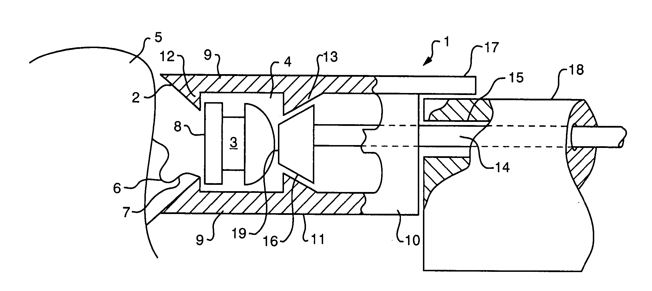
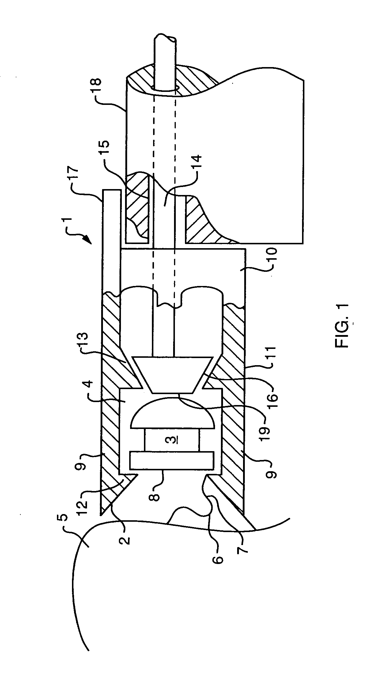
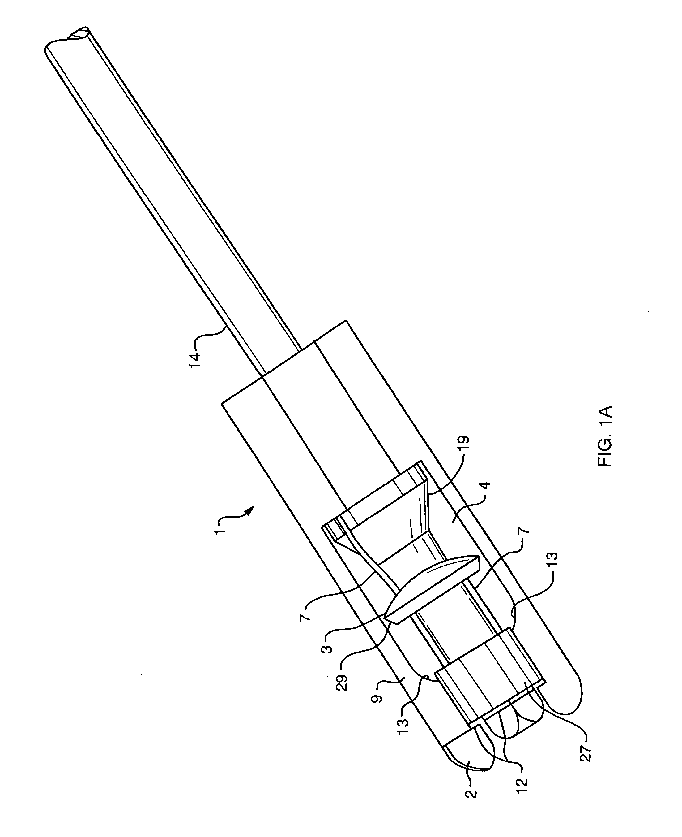
[0221] Referring to FIGS. 1-3, a clip delivery / locking device is shown generally as 1. Device 1 is shown in an embodiment designed for mounting to the distal end of an endoscope 18. Device 1 is generally cylindrical in shape and has a flange 17 extending proximally from a proximal end of device 1. Flange 17 is adapted to conform to the contours of the exterior surface of endoscope 18. The combination of the proximal end of device 1 interfacing with the distal end of endoscope 18 and flange 17 interfacing with the exterior surface of endoscope 18 effectively locks device 1 to endoscope 18. Alternatively, device 1 can be secured to endoscope 18 with mechanical fasteners.

[0222] Device 1 has portions defining a clip holding chamber 4. A proximal end 4a of holding chamber 4 (shown in FIG. 4) formed on the proximal end of device 1 communicates with holding chamber 4 and a working channel 15 of endoscope 18. Extending distally from a distal end of device 1 are fingers 9 that are oriented ...


PUM


Abstract

Suture clips and suture clip loading, delivery, locking and severing devices in both catheter and endoscopic embodiments are disclosed that permit the delivery and application of suture clips directly in contact with or in close approximation to sutured tissue. The catheter or endoscopic versions incorporate a collet cage with a plurality of flexible collet fingers that captivate a suture clip ring and a suture clip plug for assembly with a suture. An outer sliding sleeve constrains the collet fingers when distally advanced to minimize potential trauma during delivery and assembly of the suture clip in close proximity to the stitched tissue. Proximal retraction of the sliding sleeve coupled with the distal advancement of a pusher against cam surfaces on the inner walls of the collet fingers causes the collet fingers to open. The catheter is designed to hold and assemble the suture clip in a first position and release the suture clip and sever the suture ends proximal to the suture clip in a second position. Single pusher two-step embodiments and double pusher three-step embodiments are disclosed. Suture clip designs with plugs having heads for use with the suture clip delivery catheter are also disclosed. A suture clip loading device for loading suture clip components into the delivery system as well as a threader for threading sutures into the suture clip systems are also disclosed. A method of loading, delivering and deploying suture clips is further disclosed.

Description

CROSS REFERENCE TO RELATED APPLICATIONS [0001] This application is a divisional application of U.S. Ser. No. 10 / 220,413 filed Mar. 13, 2003 which is a U.S. National Stage of International Application PCT / US01 / 07349 filed Mar. 5, 2001 and published in English, which claims the benefit of U.S. provisional applications 60 / 186,926 filed Mar. 3, 2000; 60 / 205,741 filed May 19, 2000; 60 / 205,444 filed May 19, 2000 and 60 / 253,970 filed Nov. 29, 2000. The entire disclosure of the above applications are incorporated herein by reference.FIELD OF THE INVENTION [0002] The disclosed invention relates generally to devices used to secure sutures. More particularly, the invention relates to suture clips and suture clip delivery devices used in conjunction with sewing devices used in flexible endoscopy; though it is also applicable to devices used in rigid endoscopy. BACKGROUND OF THE INVENTION [0003] It is estimated that as many as 15,000,000 individuals in the United States suffer from stomach acid ...

Claims


Application Information

Patent Timeline
IPC IPC(8): A61B17/10A61B17/04
CPCA61B17/0467Y10T24/3969A61B17/0487A61B2017/0417A61B2017/0424A61B2017/0445A61B2017/045A61B2017/0451A61B2017/0454A61B2017/0456A61B2017/0459A61B2017/0464A61B2017/0488A61B2017/0496A61B17/0469
Inventor GAMBALE, RICHARD A.WEISER, MICHAEL F.PAGE, EDWARD CARLTONKOLNICK, ALEXANDER
Owner CR BARD INC
Why Eureka
Try Eureka