Vehicle diagnostic test and reporting method

a technology for vehicle diagnostics and reporting methods, applied in the field of vehicle diagnostics, can solve the problems of limited information, no directions or assistance, and little or no value for the driver of the vehicl

a technology for vehicle diagnostics and reporting methods, applied in the field of vehicle diagnostics, can solve the problems of limited information, no directions or assistance, and little or no value for the driver of the vehicl

US20070093947A1Active Publication Date: 2007-04-26GENERA MOTORS LLC

Image

  • Vehicle diagnostic test and reporting method
  • Vehicle diagnostic test and reporting method
  • Vehicle diagnostic test and reporting method

Examples


Embodiment Construction

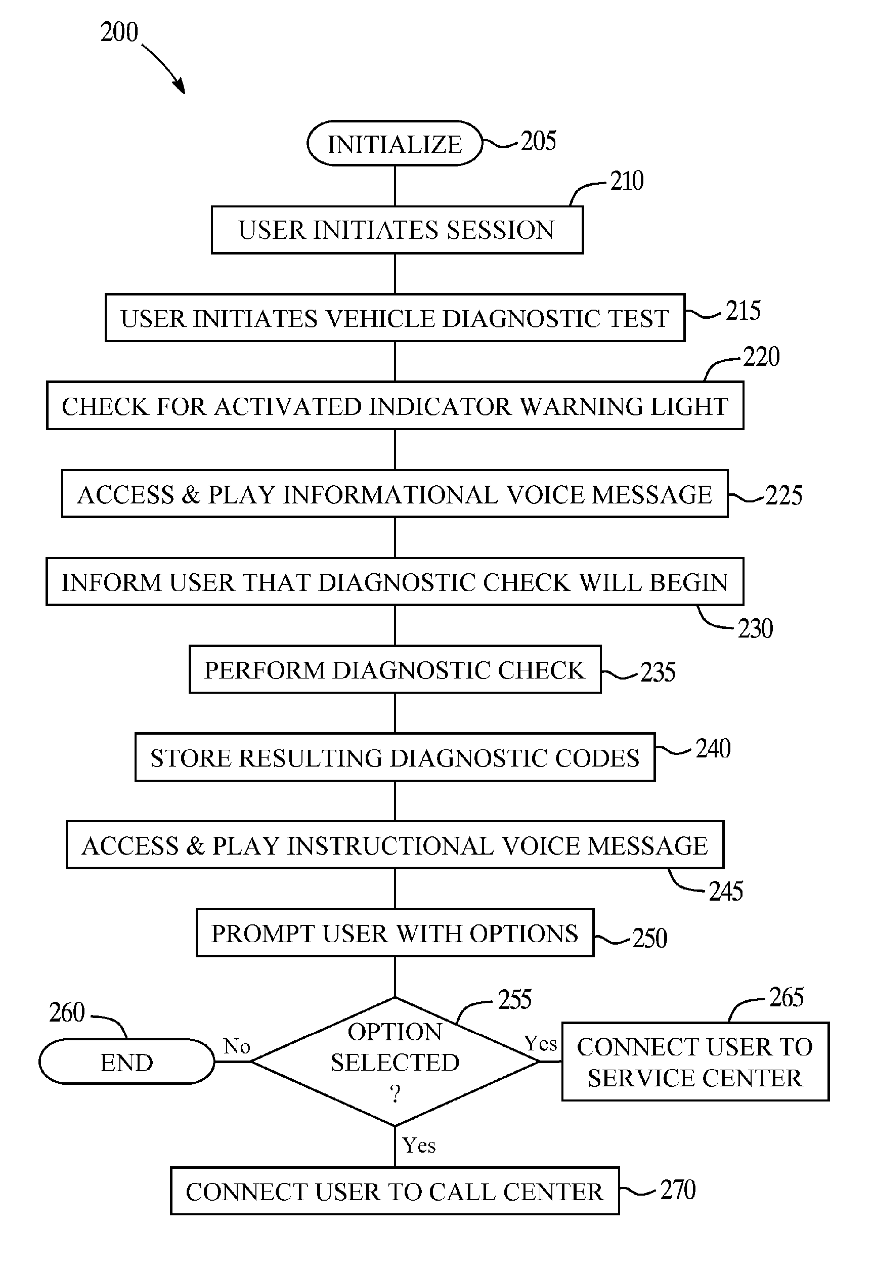
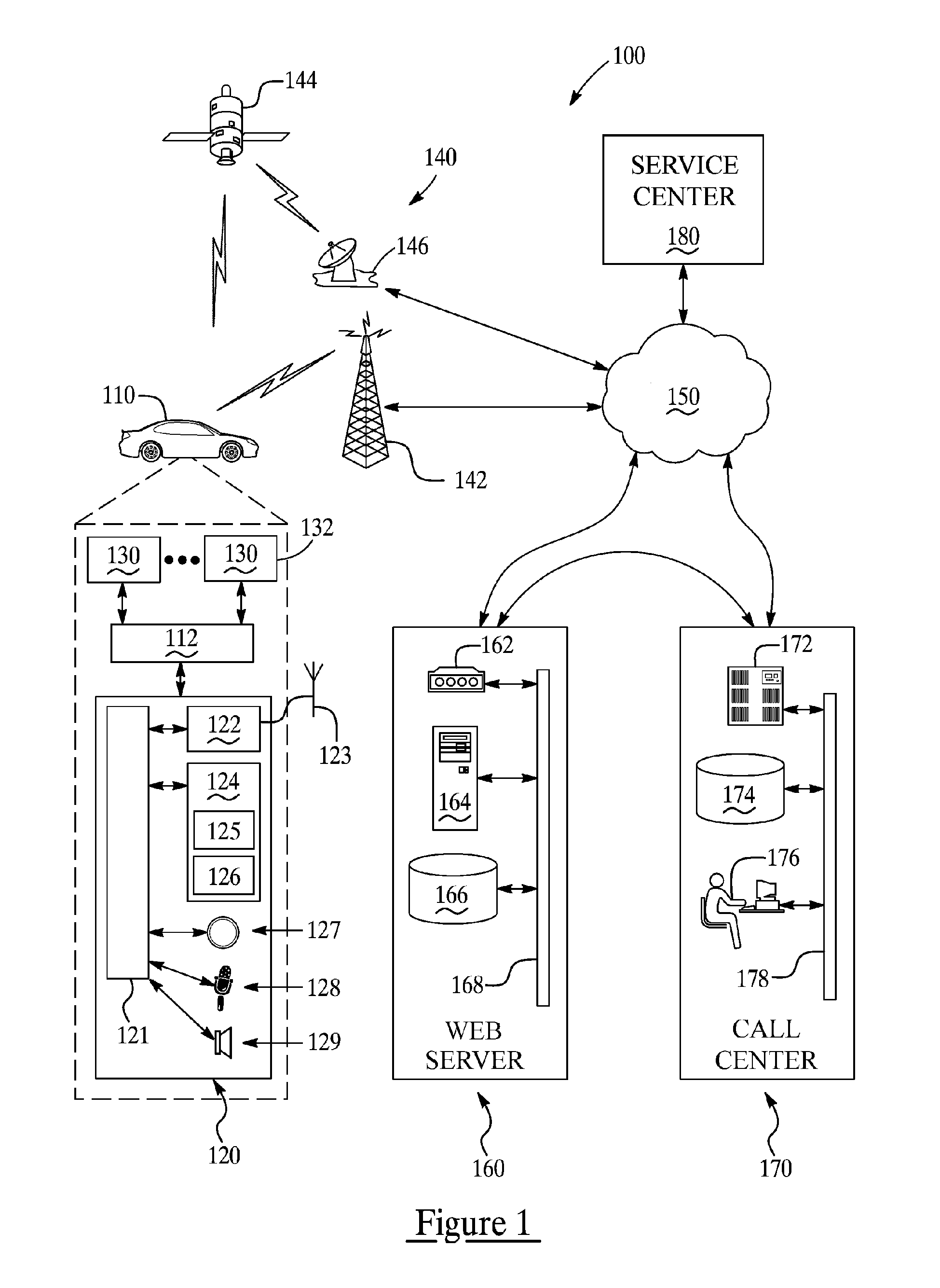
[0025] As seen in FIG. 1, there is shown an operating environment for implementing an embodiment of the method of the present invention. This embodiment utilizes a mobile vehicle communication system (MVCS) 100 which includes a motor vehicle 110, wireless carrier system 140, communication network 150, web server 160, call center 170, and vehicle service center 180. As will be described farther below in connection with FIG. 4, the particular embodiment of the inventive method described herein involves conducting various diagnostic checking and reporting within the vehicle 110, with the reporting being carried out by way of voice messages audibly played for the vehicle driver to provide information and instructions concerning various vehicle diagnostic and operating conditions. The method also enables the driver to initiate wireless voice communication with either a live advisor at the call center 170 or a service technician or scheduler (not shown) at the service center 180. The syst...


PUM


Abstract

A system and method for providing user-initiated vehicle diagnostic testing and reporting in a telematics-enabled vehicle. In the method, a request for a vehicle diagnostic test is received from the driver through a user interface of a telematics unit on the vehicle. A simplified initial diagnostic check is made and a first voice message is played for the driver that provides information concerning any detected vehicle problem. The method then undergoes a more complete diagnostic check and the resulting diagnostic information is used to select and play a second voice message that provides instructions for taking corrective action to fix the detected problem. Communication with a live advisor is also provided by way of a cellular or other wireless carrier system.

Description

TECHNICAL FIELD [0001] The invention generally relates to vehicle diagnostics and, more specifically, to diagnostic testing and reporting of operating conditions or servicing needs of a vehicle. BACKGROUND OF THE INVENTION [0002] Automobiles often include self-diagnostic capabilities to detect problems that affect engine performance, emissions, braking, and other computer controlled or monitored vehicle systems. For example, when a vehicle control module associated with a vehicle system, circuit, or component detects a fault or sensor reading outside an acceptable predefined range, the control module may generate an alphanumeric diagnostic trouble code that identifies the fault and that may be saved as diagnostic data to memory in a vehicle computer. When certain diagnostic trouble codes are received by the vehicle computer, the computer will illuminate a warning indicator light within the vehicle, such as the widely used malfunction indicator light (MIL), better known as the “Check...

Claims


Application Information

Patent Timeline
26 Apr 2007
Publication
US20070093947A1
IPC
G01M17/00; G06F19/00
CPC
G07C5/0808; G07C5/008
Inventors
GOULD, GARETT W.; MCLAURIN, GREGORY S.