Eureka AIR delivers breakthrough ideas for toughest innovation challenges, trusted by R&D personnel around the world.

Cost structure method including fuel economy and engine emission considerations

a cost structure and engine technology, applied in the direction of electrical control, process and machine control, instruments, etc., can solve the problems of high engine efficiency operating conditions and undesirably high engine emissions

Active Publication Date: 2007-04-26
GM GLOBAL TECH OPERATIONS LLC
View PDF7 Cites 221 Cited by
  • Summary
  • Abstract
  • Description
  • Claims
  • Application Information

AI Technical Summary

Problems solved by technology

However, as noted above, such high efficiency operating conditions for the engine may in fact be associated with undesirably high engine emissions.

Method used


Image

  • Cost structure method including fuel economy and engine emission considerations
  • Cost structure method including fuel economy and engine emission considerations
  • Cost structure method including fuel economy and engine emission considerations

Examples


Embodiment Construction

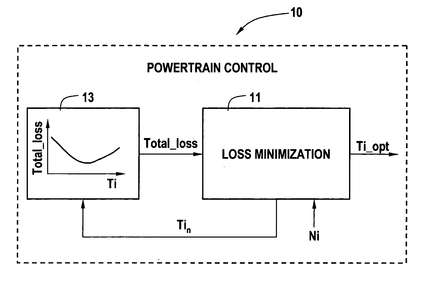
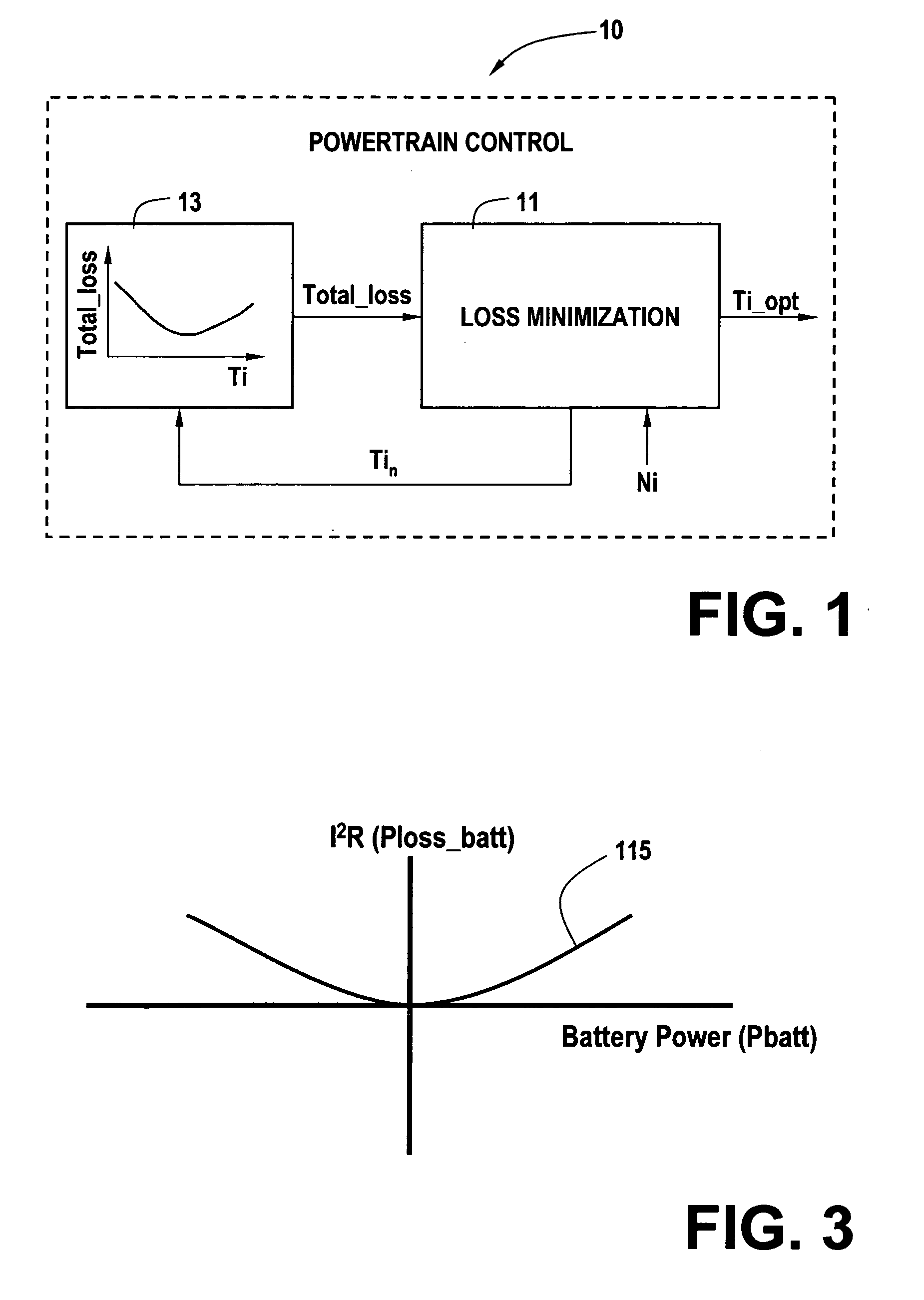
[0015] In an exemplary use or implementation of the present invention, a powertrain control for a hybrid electric vehicle establishes a preferred operating point for an internal combustion engine. For example, in FIG. 1, powertrain control 10 operating in microprocessor based control hardware (not separately shown) establishes a preferred engine torque operating point (Ti_opt) through a loss minimization routine 11. Loss minimization routine evaluates a plurality of available torque operating points (Tin) and associated aggregate powertrain system loss data (Total_loss) to establish a preferred engine torque operating point (Ti_opt). Aggregate powertrain system power loss data is referenced from predetermined data structures comprising system characterized loss data including certain objectively quantifiable power losses. Additional detail regarding such powertrain control is disclosed in detail in co-pending and commonly assigned U.S. patent application Ser. No. 10 / 779,531 now U.S....


PUM


Abstract

A powertrain control selects engine operating points in accordance with power loss minimization controls. Power loss contributions come from a variety of sources including engine power losses. Engine power losses are determined in accordance with engine operating metrics such as power production per unit fuel consumption and power production per unit emission production. Engine power losses are combined in accordance with assigned weighting into a single engine power loss term for use in the power loss minimization control and operating point selection.

Description

CROSS REFERENCE TO RELATED APPLICATIONS [0001] This application is a continuation of U.S. application Ser. No. 11 / 112,151, filed Apr. 22, 2005, which is hereby incorporated herein by reference in its entirety. The aforementioned non-provisional application claims priority to U.S. provisional patent application Ser. No. 60 / 571,664 filed on May 15, 2004, which is hereby incorporated herein by reference in its entirety.TECHNICAL FIELD [0002] The present invention is related to control of a vehicular powertrain. More particularly, the invention is concerned with balancing fuel efficiency and emissions in an internal combustion engine. BACKGROUND OF THE INVENTION [0003] An internal combustion engine can be operated at certain torque and speed combinations to achieve peak fuel efficiency. This knowledge is particularly useful in hybrid vehicle applications architected to allow for selection and control of the engine speed and torque combination as an operating point. An internal combustio...

Claims


Application Information

Patent Timeline
Patent Type & Authority Applications(United States)
IPC IPC(8): G06F17/00F02D41/14G06F19/00
CPCF02D41/1406F02D2200/1006F02D2250/18
Inventor HEAP, ANTHONY H.CAWTHORNE, WILLIAM R.HUBBARD, GREGORY A.
Owner GM GLOBAL TECH OPERATIONS LLC
Why Eureka
Eureka Blog
Learn More