Working machine management system

a management system and working machine technology, applied in the direction of traffic control system, soil-shifting machine/dredger, instruments, etc., can solve the problem of difficulty for several persons to monitor the state of use of the working machine by the joint owners

Inactive Publication Date: 2007-04-26
KOMATSU LTD
View PDF4 Cites 61 Cited by
  • Summary
  • Abstract
  • Description
  • Claims
  • Application Information

AI Technical Summary

Benefits of technology

[0005] The object of the present invention is to make it possible for a plurality of users, who share the same working machine, mutually to monitor the state of usage of the working machine by several persons.

Problems solved by technology

However, with prior art management systems, it is difficult for joint owners mutually to monitor the state of usage of a working machine by several persons.

Method used


Image

  • Working machine management system
  • Working machine management system
  • Working machine management system

Examples


Embodiment Construction

[0026] In the following, an embodiment of the present invention will be explained based on the drawings.

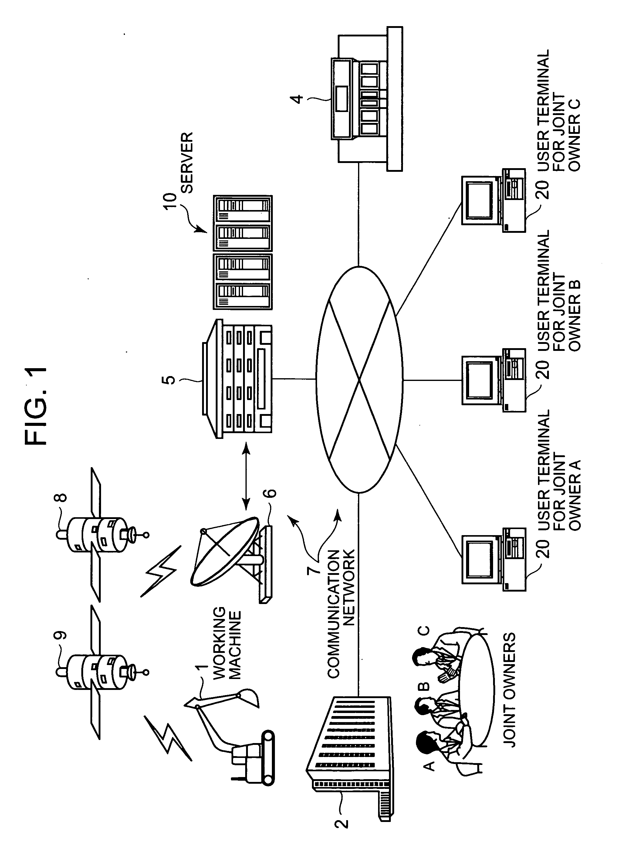
[0027]FIG. 1 is a schematic figure showing a management system for a working machine according to this embodiment.

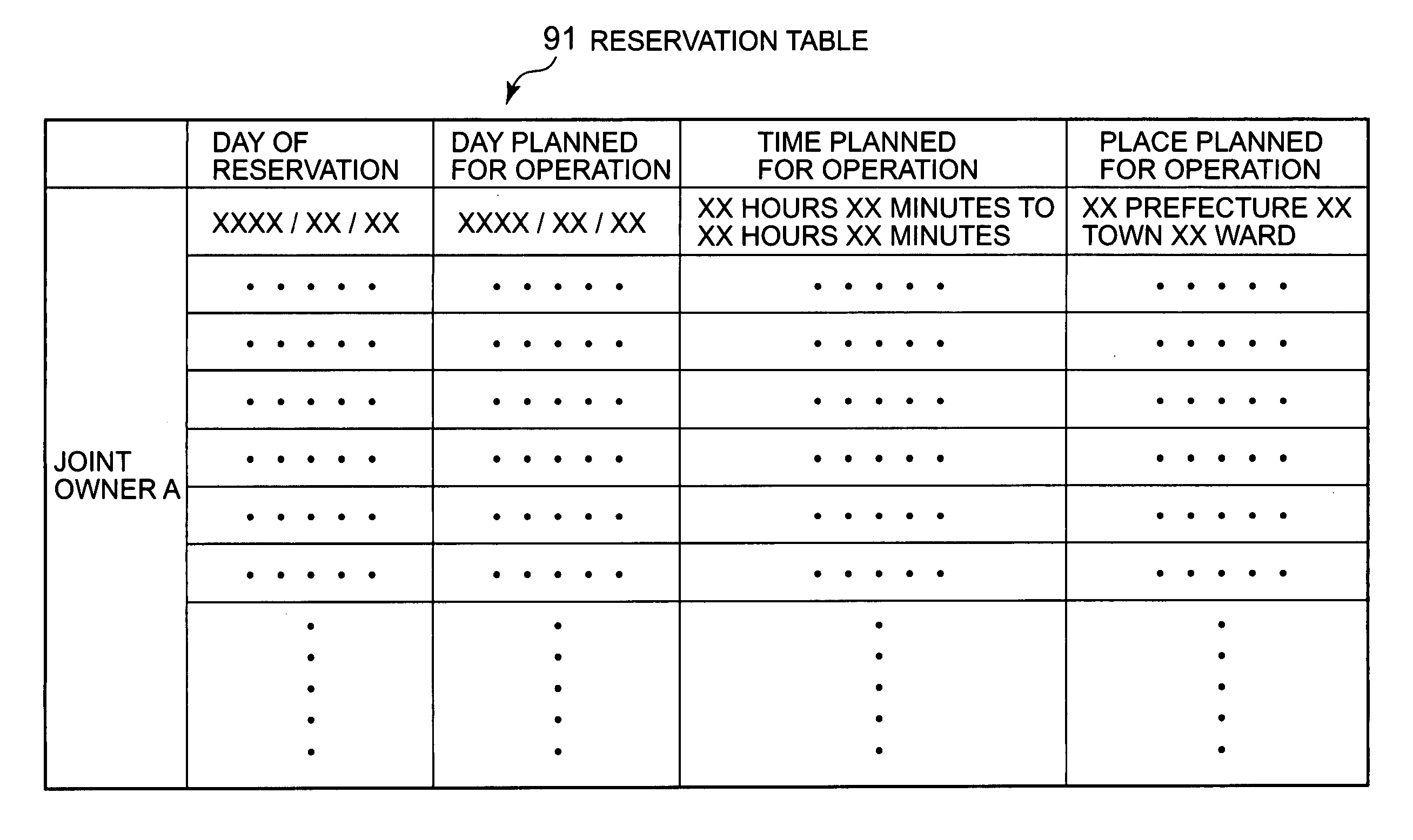
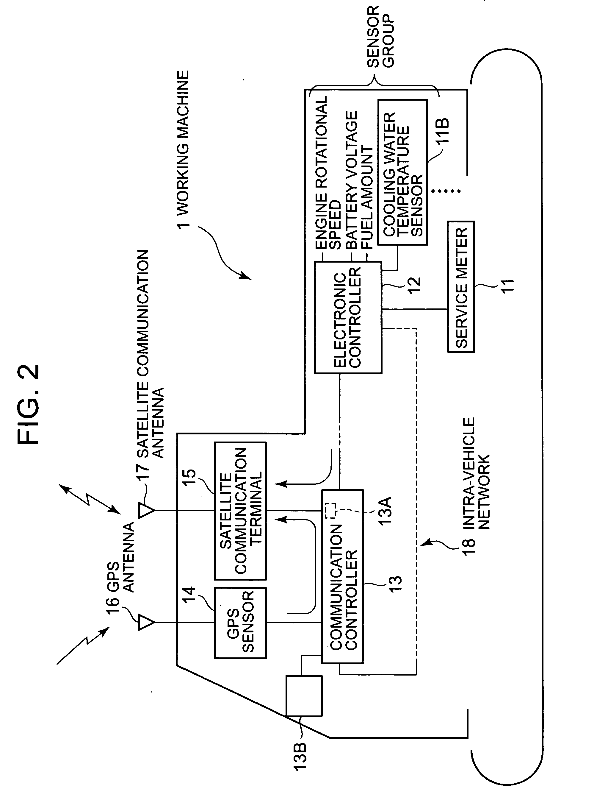
[0028] The management system of this embodiment is arranged to be able, if some working machine 1 is owned jointly by a plurality of persons (in this embodiment, three persons) A through C, to monitor, for these mutual joint owners A through C, the state of usage by several people, based on various types of operational information which are obtained from the working machine 1, and furthermore is arranged to be able to determine a usage proportion for each of the joint owners, and to determine the division between the various persons of the costs such as maintenance and the like, according to this usage proportion. And, under control by this management system, the above described costs which have been divided between of the joint owners are automatically transferred f...


PUM


Abstract

A server (10) enables users (A-B) sharing the same working machine (1) to mutually monitor a usage state by each user. The server (10) receives a user ID, the working time, the engine cooling water temperature, and the current position that are detected in the working machine (1) through a satellite communication network, and calculates the usage time, the usage location, the load amount, and a usage proportion for each user. The server (10) sends a warning to the user terminals 20 when the usage time or location is not as planned, or the load amount is excessive. The server (10) periodically reports the usage times and locations, the load amounts, and the usage proportions for the users (A-B) to the user terminals (20). The server (10) allocates maintenance costs of the working machine (1) automatically between the users (A-B) according to the usage proportions of the users (A-B).

Description

TECHNICAL FIELD [0001] The present invention relates to a management system for a working machine such as a construction machine or one for transportation work or the like. BACKGROUND ART [0002] Management systems are known (for example, Patent Document #1) which manage collectively the operational states of working machines such as a large number of construction machines or transportation vehicles or the like which are present in several locations. With these management systems, various types of sensor are mounted on the working machines, and operational data (data such as, for example, working time, engine rotational speed, battery voltage, engine cooling water temperature, remaining amount of fuel and the like) are generated based on the detection signals from those sensors. This operational data for the working machines is gathered by a server via a computer network which includes a wireless communication network. And the server accumulates the operational data for the working m...

Claims


Application Information

Patent Timeline
Patent Type & Authority Applications(United States)
IPC IPC(8): G06Q10/00E02F9/20G06Q10/02G06Q10/06G07C5/00G08G1/123
CPCE02F9/2025G06Q10/02G06Q10/0631G07C5/008G08G1/123
Inventor NAKAYAMA, TETSUYAARAKAWA, SHUJINISHIKAWA, YUKIEKOIZUMI, HIDENORI
Owner KOMATSU LTD
Why Eureka
Try Eureka