Pumping System for Atomic Layer Deposition

a vacuum pumping system and atomic layer technology, applied in the direction of mechanical equipment, water supply installation, transportation and packaging, etc., can solve the problems of debilitating or destroying the vacuum pumping system, forming undesired deposits and/or particles, and without adequate controls

Inactive Publication Date: 2007-05-03
GALEWSKI CARL JOHAN
View PDF3 Cites 283 Cited by
  • Summary
  • Abstract
  • Description
  • Claims
  • Application Information

AI Technical Summary

Benefits of technology

[0015] According to another aspect of the invention, an adjustable valve is provided for evacuating a reactive precursor from a reactive region in a semiconductor thin film process chamber. The adjustable valve includes a first perforated component rendered stationary within the process chamber, and a second perforated component geometrically similar to the first perforated component, the second perforated component rotable within the chamber to align one or more of the perforations common to both components to form one or more pathways through the valve and rotable within the chamber to misalign all of the perforations common to both components to prevent pathways through the valve.

Problems solved by technology

When mixed in gas phase, those components react violently and without adequate controls can form undesired deposits and / or particles deposited directly out of the gas phase.
In some cases these deposits and / or particles can debilitate or destroy a vacuum pumping system.
This introduces another problem in that the inefficient use of a gas reactant is not only costly but also increases the possibility of undesired reaction in the exhaust from the chamber.
This inefficiency factor contributes to increased maintenance, not withstanding risk to vacuum pumps and elevated “scrubbing” requirements before exhaust can be released to atmosphere.
Cycling a physical mass at those speeds is challenging by itself.
However, moving a larger device that can regulate a large cross-section separating a reactive and an exhaust region in an ALD apparatus can be much more challenging.
Use of gas injected by small valves and flow restrictors has been proposed, but may suffer from being difficult to set up and operate consistently over time.
However, implementation of these mechanical means as suggested may actually increase formation of particles from physical contact between moving members or increased opportunity for unwanted reactions in the exhaust region.

Method used


Image

  • Pumping System for Atomic Layer Deposition
  • Pumping System for Atomic Layer Deposition
  • Pumping System for Atomic Layer Deposition

Examples


Embodiment Construction

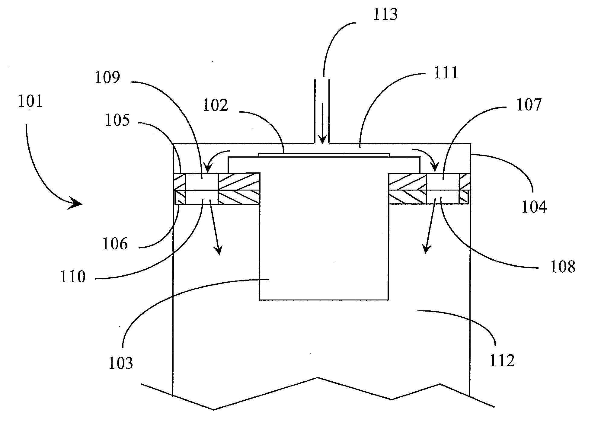
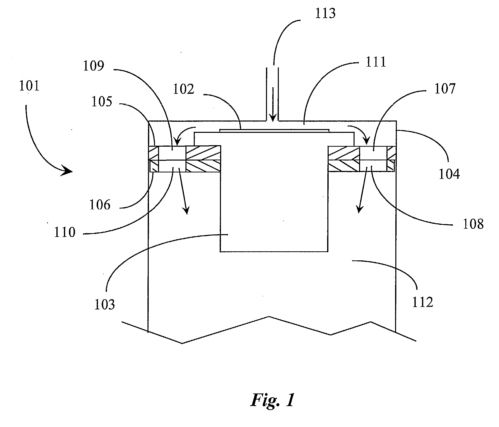
[0025]FIG. 1 is an elevation section view of an atomic layer deposition apparatus according to an embodiment of the present invention. Atomic Layer Deposition (ALD) apparatus 101 is logically illustrated in this example as representative of a typical ALD processing environment including a stationary hearth and frame structure 103 that supports a workpiece 102 that will be developed with thin films. Hearth 103 and workpiece 102 are, during processing, enclosed in a vacuum-tight ALD chamber 104 as is typical in the art. Workpieces 102 may be a silicon wafer or a wide variety of other types of workpieces that may be coated.

[0026] Chamber 104 may be provided in aluminum, stainless steel, or any other durable material known to be applicable in ALD processing. Workpiece 102 is assumed to be pre-treated with an agent that will react with an introduced reactive gas. Chamber 104 has an input valve 113, through which gasses are introduced into a process region, also called a reactive region ...


PUM

PropertyMeasurementUnit
temperatureaaaaaaaaaa
diameteraaaaaaaaaa
volumesaaaaaaaaaa

Abstract

A pumping apparatus for evacuating a reactant from a reactive region includes a vacuum able chamber, a hearth for supporting a workpiece, one or more gas introduction valves, one or more exhaust evacuation valves, and an adjustable valve providing one or more pathways there through formed by alignment of separate components of the valve, the components perforated with two or more openings to form the pathways.

Description

CROSS-REFERENCE TO RELATED APPLICATIONS [0001] The present invention claims priority to a U.S. provisional patent application Ser. No. 60 / 732,428 filed on Oct. 31, 2005 entitled “ALD Pumping System” which is included herein at least by reference.BACKGROUND OF THE INVENTION [0002] 1. Field of the Invention [0003] The present invention is in the field of semiconductor manufacturing equipment used in chemical vapor deposition (CVD) processes including a category of CVD known as Atomic Layer Deposition (ALD). The invention pertains particularly to methods and apparatus for regulating and manipulating purge exhaust pumping steps between reactive vapor deposition steps. [0004] 2. Discussion of the State of the Art [0005] ALD processing encompasses one or more time-separated pulses of gas reactants, typically including but not limited to reactive gases, that react with a surface treatment of a work piece to provide deposition of a thin film of material resultant of the reaction. Usually ga...

Claims


Application Information

Patent Timeline
Patent Type & Authority Applications(United States)
IPC IPC(8): F17D1/00H01L21/306C23C16/00
CPCC23C16/4412C23C16/45544C23C16/4585Y10T137/0318
Inventor GALEWSKI, CARL JOHAN
Owner GALEWSKI CARL JOHAN
Why Eureka
Try Eureka