Vehicular brake device

Inactive Publication Date: 2007-05-03
ADVICS CO LTD
View PDF3 Cites 18 Cited by
  • Summary
  • Abstract
  • Description
  • Claims
  • Application Information

AI Technical Summary

Benefits of technology

[0011] Since the spring is located between the first case and the second case, space can be more effectively utilized, as compared to locating the spring at an end or base of the pump body. A total axial length (pump shaft length) of the pump body including the spring can thus

Problems solved by technology

However, considerable variations in the axial force may occur when the above axial force is generated by thread fasteni

Method used


Image

  • Vehicular brake device
  • Vehicular brake device
  • Vehicular brake device

Examples


Embodiment Construction

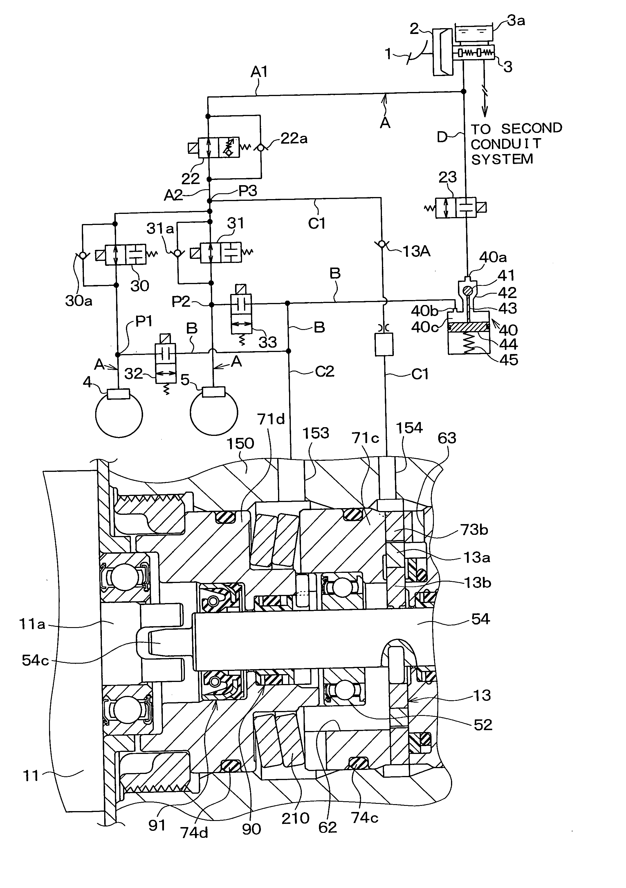
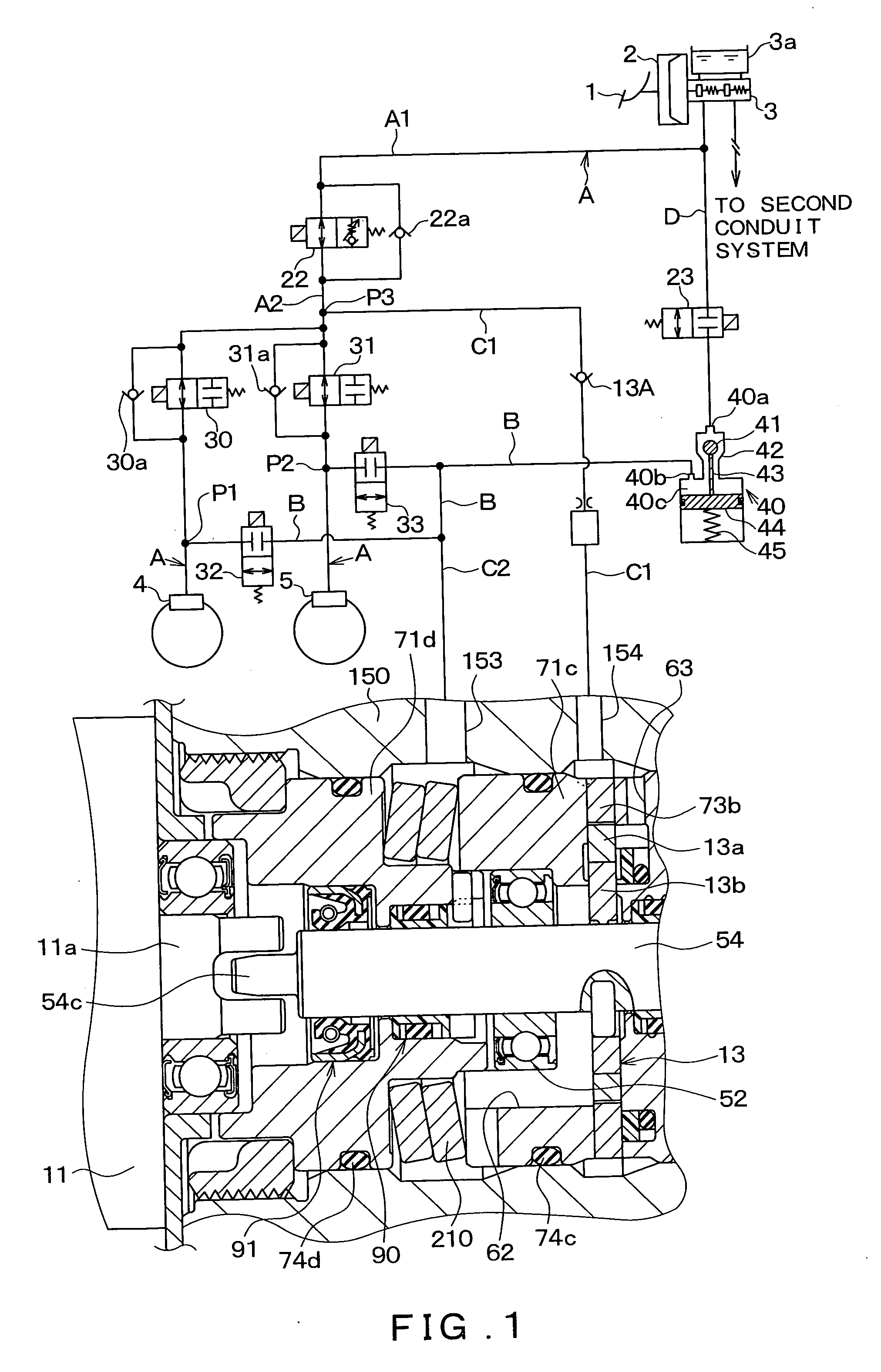
[0019] A basic configuration of the brake device according to an embodiment of the present invention will be described below with reference to FIG. 1. An internal pump (specifically, a trochoid pump) is used as a rotary pump of the brake device shown in FIG. 1. In the following description, the brake device is applied to a front-wheel-drive four-wheel vehicle having an X type hydraulic circuit which includes a first conduit system for both the front right wheel and the rear left wheel, and a second conduit system for both the front left wheel and the rear right wheel. However, the brake device may also be applied to a vehicle having a front-rear type hydraulic circuit which includes a conduit system for both the front right wheel, and the rear right wheel and another conduit system for both the front left wheel and the rear left wheel and to a vehicle having any other type of hydraulic circuit.

[0020] As shown in FIG. 1, a brake pedal 1 is connected with a booster 2, which amplifies...


PUM


Abstract

A pump body includes a cylindrical first case for housing the plurality of rotary pumps, a second case located coaxially with the first case, and a disk spring located between the first case and the second case. In addition, a fixing means located at an entrance of the concave portion of a housing presses the second case in the insertion direction of the pump body and fixes the second case.

Description

CROSS REFERENCE TO RELATED APPLICATION [0001] This application is based on and incorporates herein by reference Japanese Patent applications No. 2005-318438 filed on Nov. 11, 2005, No. 2005-318439 filed on Nov. 11, 2005, No. 2006-101949 filed on Apr. 3, 2006, No. 2006-101950 filed on Apr. 3, 2006, and No. 2006-101951 filed on Apr. 3, 2006. FIELD OF THE INVENTION [0002] The present invention relates to a vehicular brake device that uses a rotary pump such as a trochoid pump in performing brake hydraulic control. BACKGROUND OF THE INVENTION [0003] Efforts have been made in recent years to reduce operation noise and the like during a brake hydraulic pressure control such as ABS control. For this purpose, a rotary pump such as a trochoid pump is used in a vehicular brake device as a pump for the brake hydraulic pressure control. [0004] A vehicular brake device having such a rotary pump is proposed in Japanese Patent Publication No. 2001-80498. FIG. 5 is a cross sectional view of a pump ...

Claims


Application Information

Patent Timeline
IPC IPC(8): B60T13/16
CPCB60T8/4031B60T17/02F04C2/10F04C11/001F04C15/0084
Inventor YAMAGUCHI, TAKAHIROFUCHIDA, TAKESHITORII, SHIGEKISATO, TAKASHIIKAI, HIDEMIISHIKAWA, YUKIOSHINKAI, HIROYUKI
Owner ADVICS CO LTD
Why Eureka
Try Eureka