Multi-phase electrical motor for use in a wheel

a multi-phase, electric motor technology, applied in the direction of electric vehicles, dynamo-electric machines, battery/cell propulsion, etc., can solve the problem of unsatisfactory motor vibration

Active Publication Date: 2007-05-03
GREENEE ENERGIE INC GREENEE ENERGY
View PDF34 Cites 22 Cited by
  • Summary
  • Abstract
  • Description
  • Claims
  • Application Information

AI Technical Summary

Benefits of technology

[0009] It is an object of the invention to provide a rotary muti-phase electrical motor that overcomes at least some of the inconveniences of the prior art.

Problems solved by technology

Previous configurations of brushless electrical motor with stator sections present somewhat high magnitude of cogging torque which causes undesirable motor vibrations.

Method used


Image

  • Multi-phase electrical motor for use in a wheel
  • Multi-phase electrical motor for use in a wheel
  • Multi-phase electrical motor for use in a wheel

Examples


Embodiment Construction

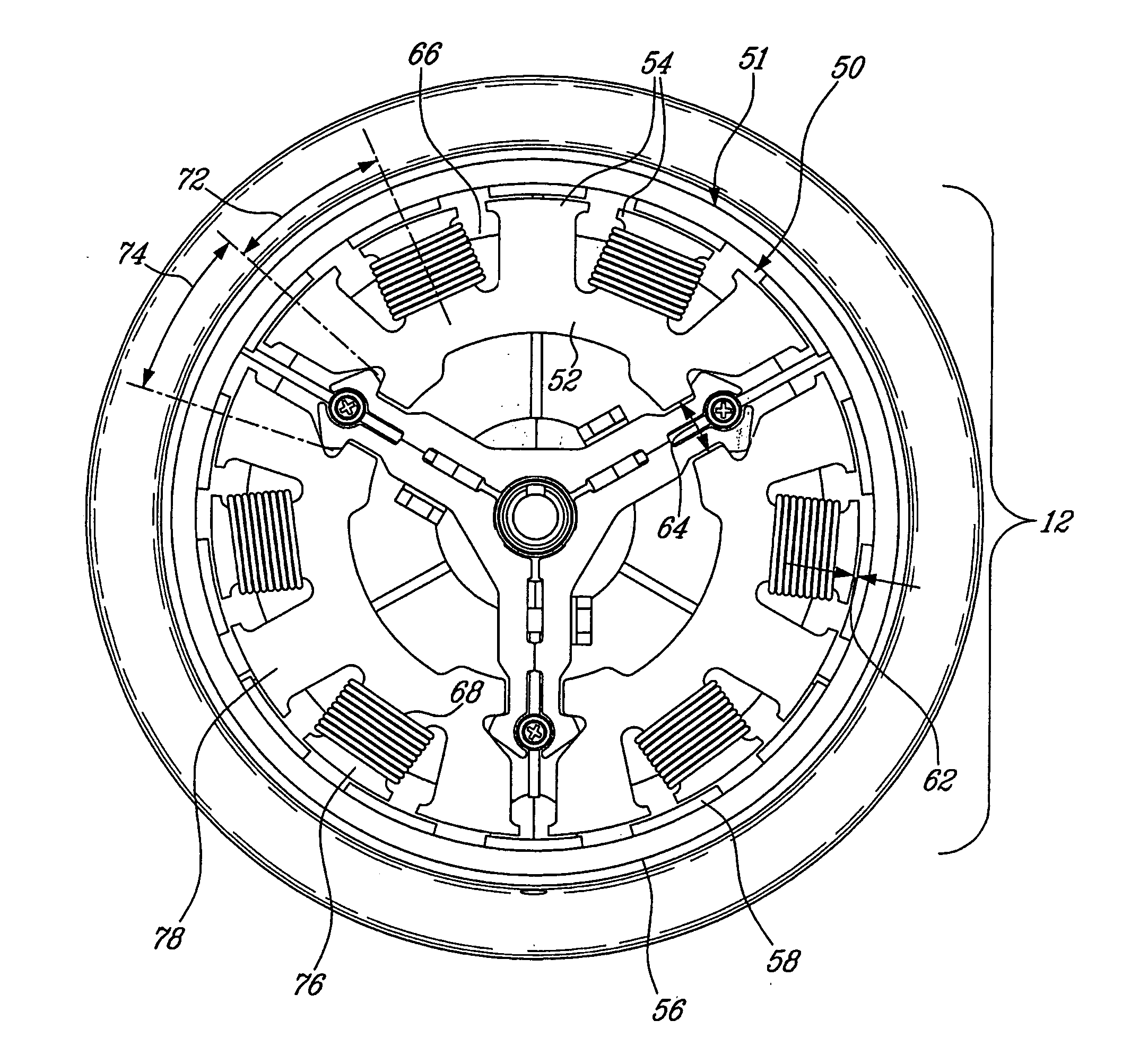
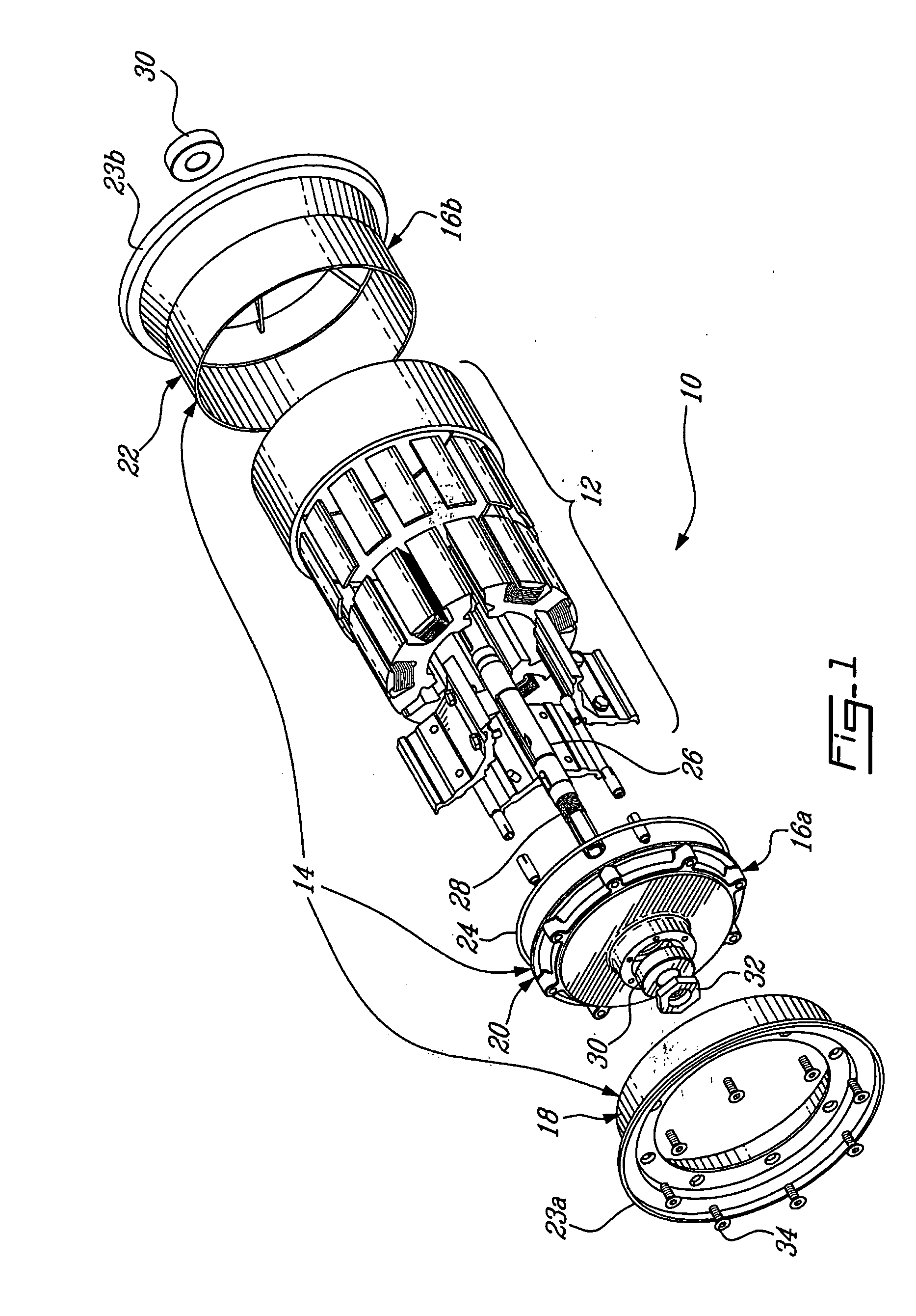
[0026] Referring to the drawings, FIG. 1 illustrates a wheel motor 10 for driving a vehicle. The wheel motor 10 is rotatively powered by a rotary electrical motor 12 encased in a wheel frame, which is in this case a demountable rim 14. The demountable rim 14 and the electrical motor 12 are both mounted on a main static shaft 26 that connects the wheel motor 10 to a vehicle.

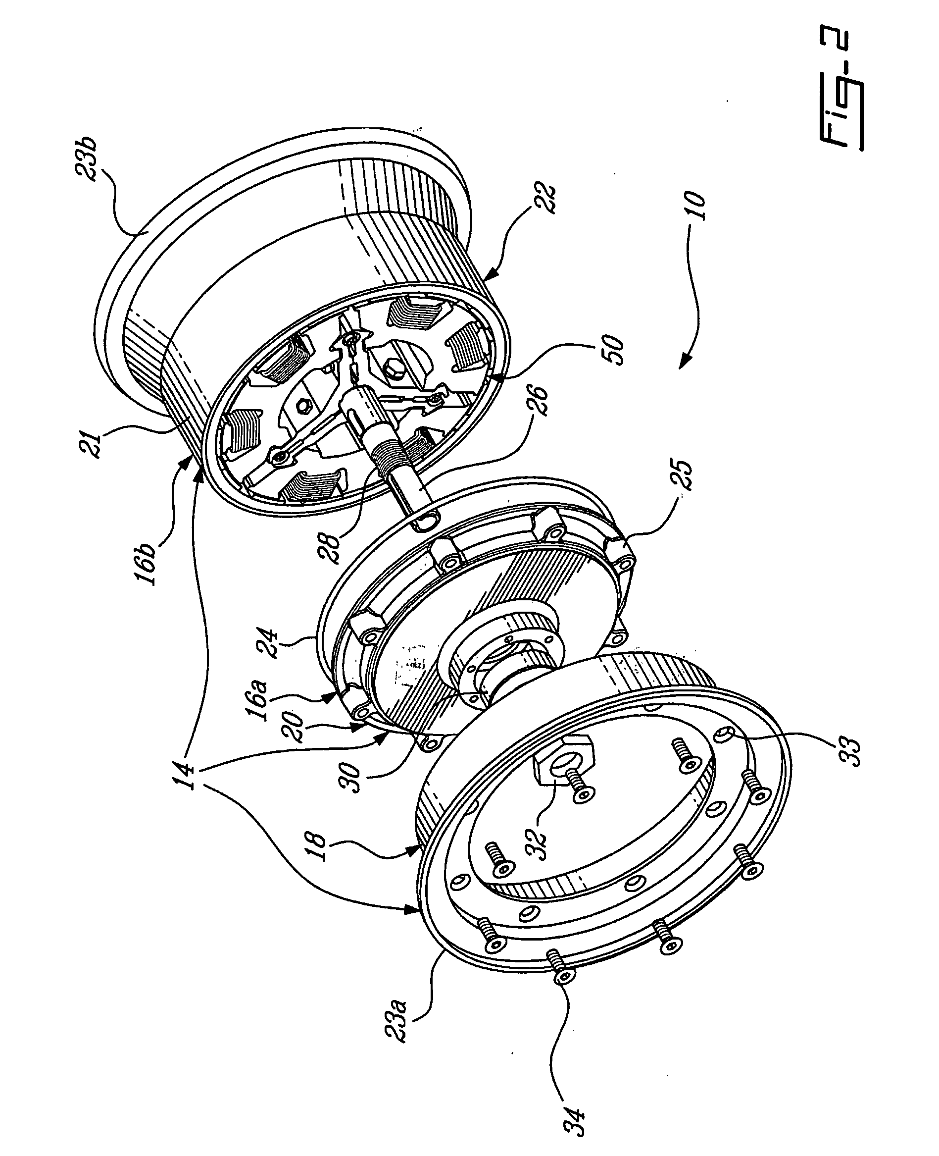
[0027] The demountable rim 14 mainly consists of a motor casing 16a, 16b and a removable outer rim 18 that can be removed from the casing outwardly relative to the vehicle. The motor casing 16a, 16b is composed of an inner rim 22 and a cover 20 that fit together to enclose and protect the electrical motor 12. The demountable rim 14 is designed to bear a pneumatic tire using the cooperating inner rim 22 and removable outer rim 18, as illustrated on FIG. 3.

[0028] In FIG. 2, the electrical motor 12 is shown assembled and encased in the casing. The demountable rim 14 including the motor casing 16a, 16b and the remov...


PUM


Abstract

The invention relates to a rotary multi-phase electrical motor wherein stator teeth corresponding to one same phase are grouped on a distinct and magnetically isolated stator section. The number of teeth per stator section is an odd number of a value of at least three and the difference between the total number of stator teeth and the number of rotor permanent magnet poles is one. The teeth are preferably equidistantly distributed along the stator. The invention also relates to a wheel motor using the rotary multi-phase electrical motor described above.

Description

BACKGROUND OF THE INVENTION [0001] 1) Field of the Invention [0002] The invention relates to rotary brushless electrical motors. More particularly, the invention relates to a motor having magnetically isolated stator sections. [0003] 2) Description of the Prior Art [0004] In traditional configurations of brushless electrical motors having a stator with coiled stator teeth and a rotor with permanent magnet poles, coils are driven by multiple phases and phases overlap one another on stator teeth. U.S. Pat. No. 4,774,428 to Konecny describes a rotary motor configuration where coils driven by the same phase are grouped on proximate teeth to occupy one distinct portion of the stator. Konecny explains that this phase grouping reduces electromagnetic torque ripple and increases starting torque per unit of volume of wire. This motor have a single stator magnetic circuit with teeth substantially equidistantly distributed. In this winding configuration, one coil is wound around each tooth. [0...

Claims


Application Information

Patent Timeline
Patent Type & Authority Applications(United States)
IPC IPC(8): H02K1/32B60K1/00H02K7/00
CPCB60K7/0007B60L11/1803B60L2220/44Y02T10/7005H02K1/148H02K1/187Y02T10/641H02K1/14B60L50/51Y02T10/64Y02T10/70
Inventor CROS, JEROMEMATTE, DENISVIAROUGE, PHILIPPE
Owner GREENEE ENERGIE INC GREENEE ENERGY
Why Eureka
Try Eureka