Multichannel flat tube for heat exchanger

a heat exchanger and multi-channel technology, applied in the direction of discharge tube main electrodes, incadescent cooling arrangements, lighting and heating apparatus, etc., can solve the problems of high heat conduction loss between the flow channels, unsatisfactory proportion of heat transport, and inevitable heat conduction along the width of the flat tube, so as to reduce the material cross-section, heat conduction, and enhanced heat transmission efficiency

Active Publication Date: 2007-05-03
HANON SYST
View PDF7 Cites 19 Cited by
  • Summary
  • Abstract
  • Description
  • Claims
  • Application Information

AI Technical Summary

Benefits of technology

[0024] The advantages of the invention are that by reducing the material cross-section in the flat tube, heat conduction along the flow direction of the fluid that passes around the flat tube along its width is reduced. That yields significantly enhanced heat transmission efficiency.

Problems solved by technology

As the flat tube is usually formed of a material that is a good heat conductor, heat conduction along the width of the flat tube inevitably occurs.
Reducing the heat transfer efficiency, this proportion of heat transport is not desirable.
The refrigerant flows in opposite flow directions at least once, or several times. Hence high temperature differences can occur between neighboring flow channels that cause high heat conduction losses between the flow channels.
Manufacture of heat transfer devices with separate flat tubes that are series-connected in direction of the air flow and have no contact surfaces to each other is very expensive.
The known flat tubes according to the generic term feature high transverse heat conduction and for that reason, are not really suitable for heat transfer devices working on cross flow principle.
Particularly disadvantageous is the reduced static loadability of said multi-channel flat tube that makes the tube become unstable.
Also the increased space requirement of a too wide web is not desired.

Method used


Image

  • Multichannel flat tube for heat exchanger
  • Multichannel flat tube for heat exchanger
  • Multichannel flat tube for heat exchanger

Examples


Embodiment Construction

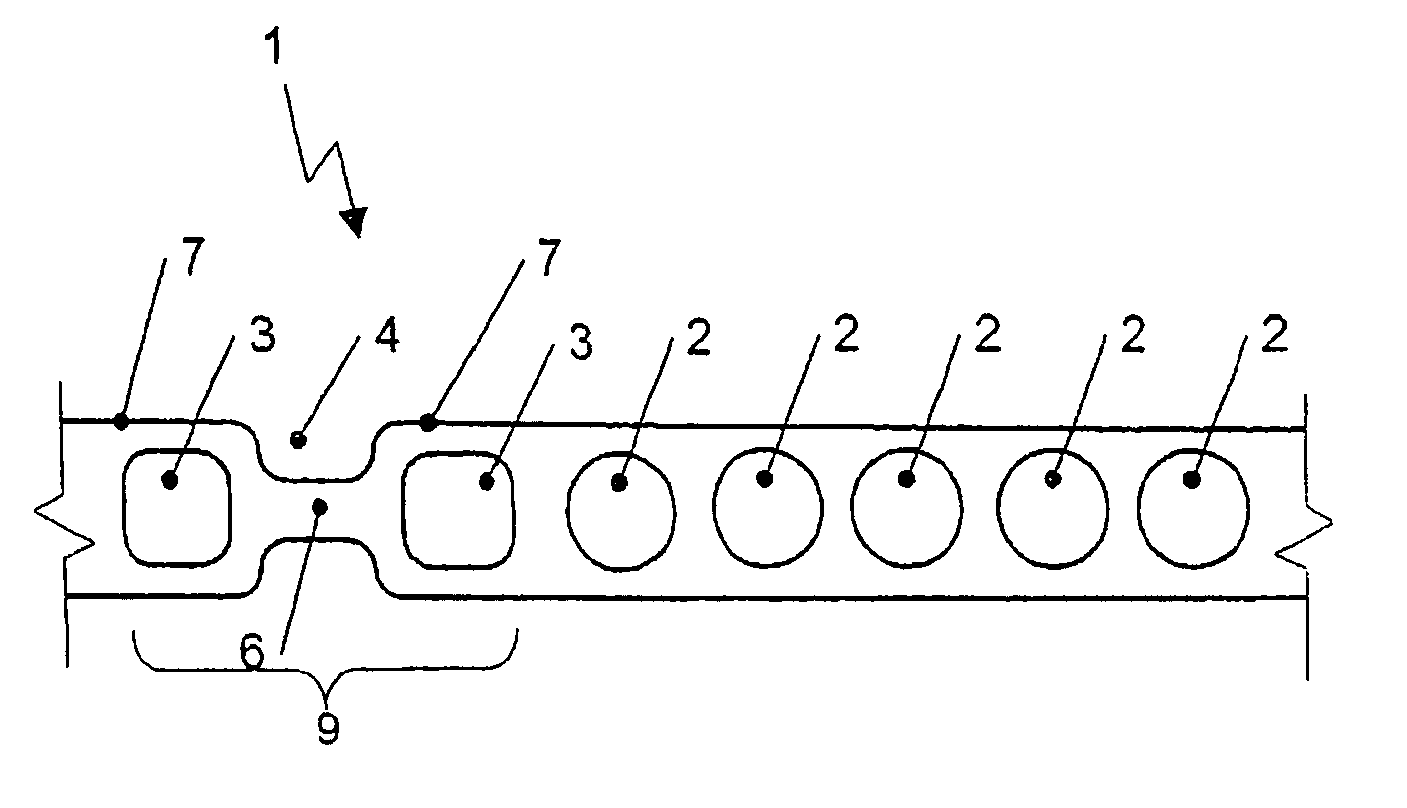
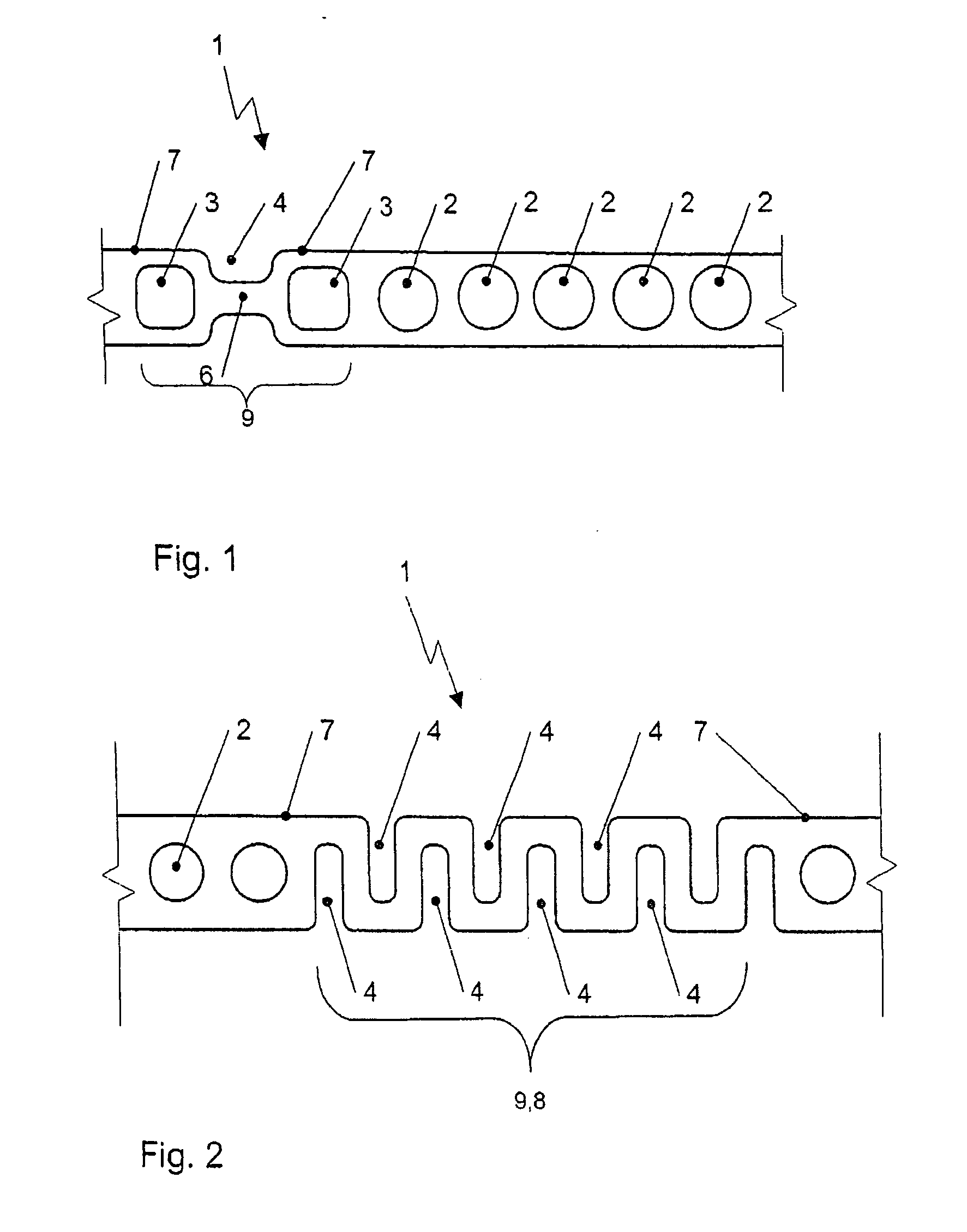
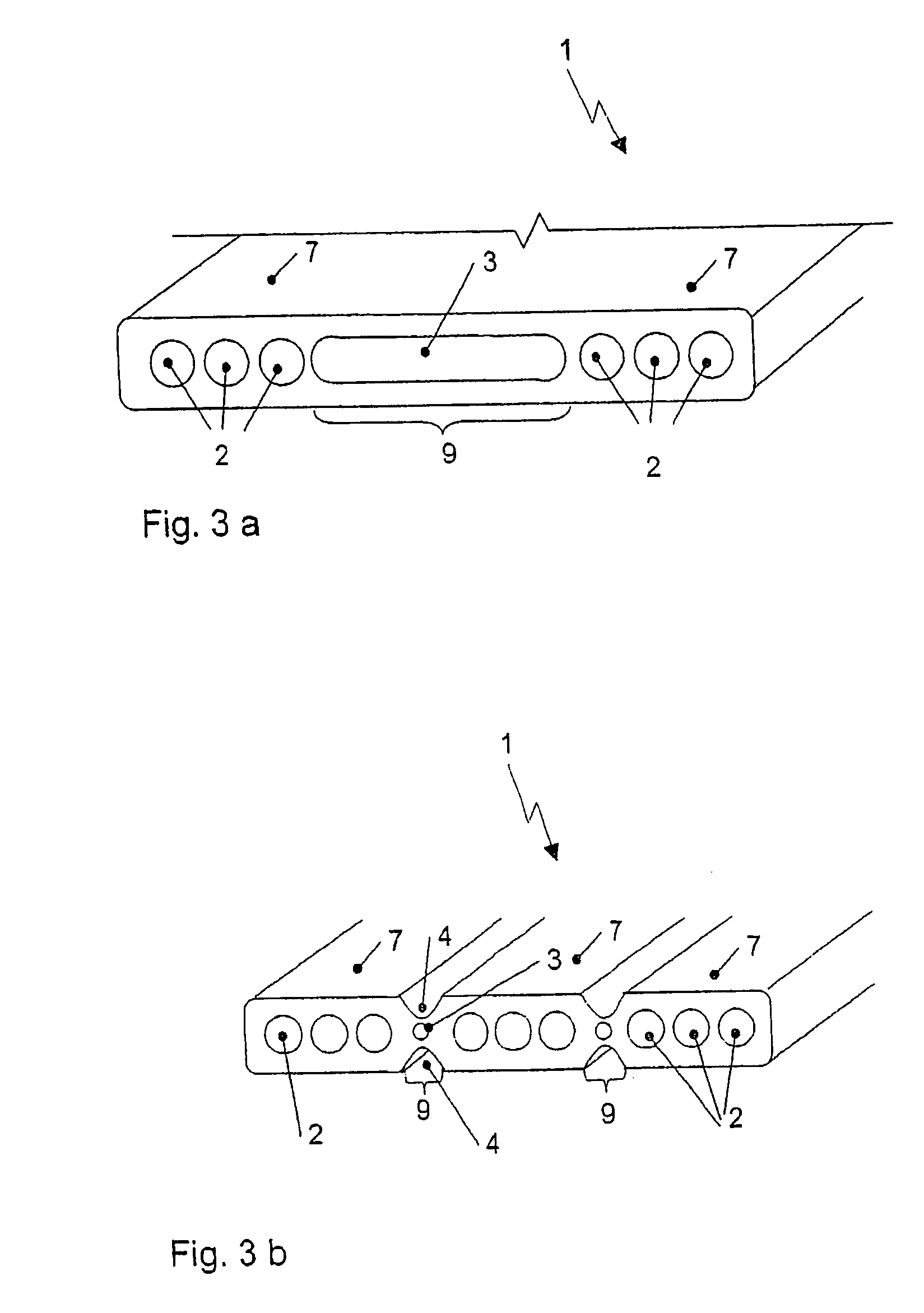
[0036] In FIG. 1, a cross-sectional view of a multi-channel flat tube 1 with a region of reduced heat transmission with connecting web and two isolating channels is shown. The multi-channel flat tube 1 is shown only in parts of its cross-section to identify the peculiarities of the region of reduced heat transmission 9. The region of reduced heat transmission 9 separates the channel sections 7 from each other. To ensure particularly efficient separation, constrictions 4 are provided in the multi-channel flat tube 1 that lead to formation of the connecting web 6. This measure is completed by use of two isolating channels 3 that are located on both sides of the connecting web 6, together with the constrictions 4 forming the region of reduced heat transmission 9.

[0037] In FIG. 2, as an alternative design, the region of reduced heat transmission 9 is configured as a meander-shaped connecting web 8. Here for separating the channel sections 7 with the respective channels 2, the multi-cha...


PUM


Abstract

The invention relates to a multi-channel flat tube for heat exchangers that contains at least two channels extending along its length and arranged essentially adjacent to each other along its width passable by fluid, or at least two channel sections formed by one or several of said channels, whereby between the channels or the channel sections over the length of the flat tube one region of reduced heat transmission in each case is provided, characterized by that the region of reduced heat transmission is defined by a connecting web and isolating channels arranged on both sides of the connecting web. The transverse heat conduction within the flat tube is reduced by this arrangement.

Description

CROSS-REFERENCE TO RELATED APPLICATION [0001] This application claims priority to German Patent Application Serial Number 102005052683.7, filed Oct. 27, 2005, the entire disclosure of which is hereby incorporated herein by reference. FIELD OF THE INVENTION [0002] The invention relates to a multi-channel flat tube for heat exchangers that is particularly used in refrigeration plants and heat pumps working with high-pressure refrigerants. BACKGROUND OF THE INVENTION [0003] Multi-channel flat tubes and heat exchangers containing such tubes are known in the art. In DE 100 07 159 A1 a cooler and evaporator tube is disclosed that is characterized by a special cross-section of the channels in the flat tube. The number of channels in the flat tube is not given more precise, these channels extending in longitudinal direction of the flat tube. [0004] Further, to DE 197 19 260 C1 a stamped flat tube is known in the art that also consists of several channels and is equipped with additional webs...

Claims


Application Information

Patent Timeline
Patent Type & Authority Applications(United States)
IPC IPC(8): H01J61/52H01J7/24H01J1/02
CPCF16L9/19F28F1/022F28F1/025F28F13/00F28F2270/00
Inventor ANTONIJEVIC, DRAGIHOFFMANN, HANSKARL
Owner HANON SYST
Why Eureka
Try Eureka