Camera module

a technology of camera module and camera body, applied in the field of camera module, can solve the problems of affecting the quality of the image, the degradation of the synthesized image, and the increase of the image processing time, so as to achieve the effect of favorable productivity, accurate measurement of distance to a subject, and high quality

Inactive Publication Date: 2007-05-03
PANASONIC CORP
View PDF17 Cites 53 Cited by
  • Summary
  • Abstract
  • Description
  • Claims
  • Application Information

AI Technical Summary

Benefits of technology

[0023] According to the present invention, even when the ambient temperature changes, a relative displacement between a single lens and the corresponding imaging region is slight. Therefore, a high quality image can be obtained stably irr

Problems solved by technology

However, since sensitivity and a saturation power of a solid-state imaging device are in proportion to a pixel size, there is a limit to decreasing a pixel pitch.
However, if a position of a lens

Method used


Image

  • Camera module
  • Camera module
  • Camera module

Examples


embodiment 1

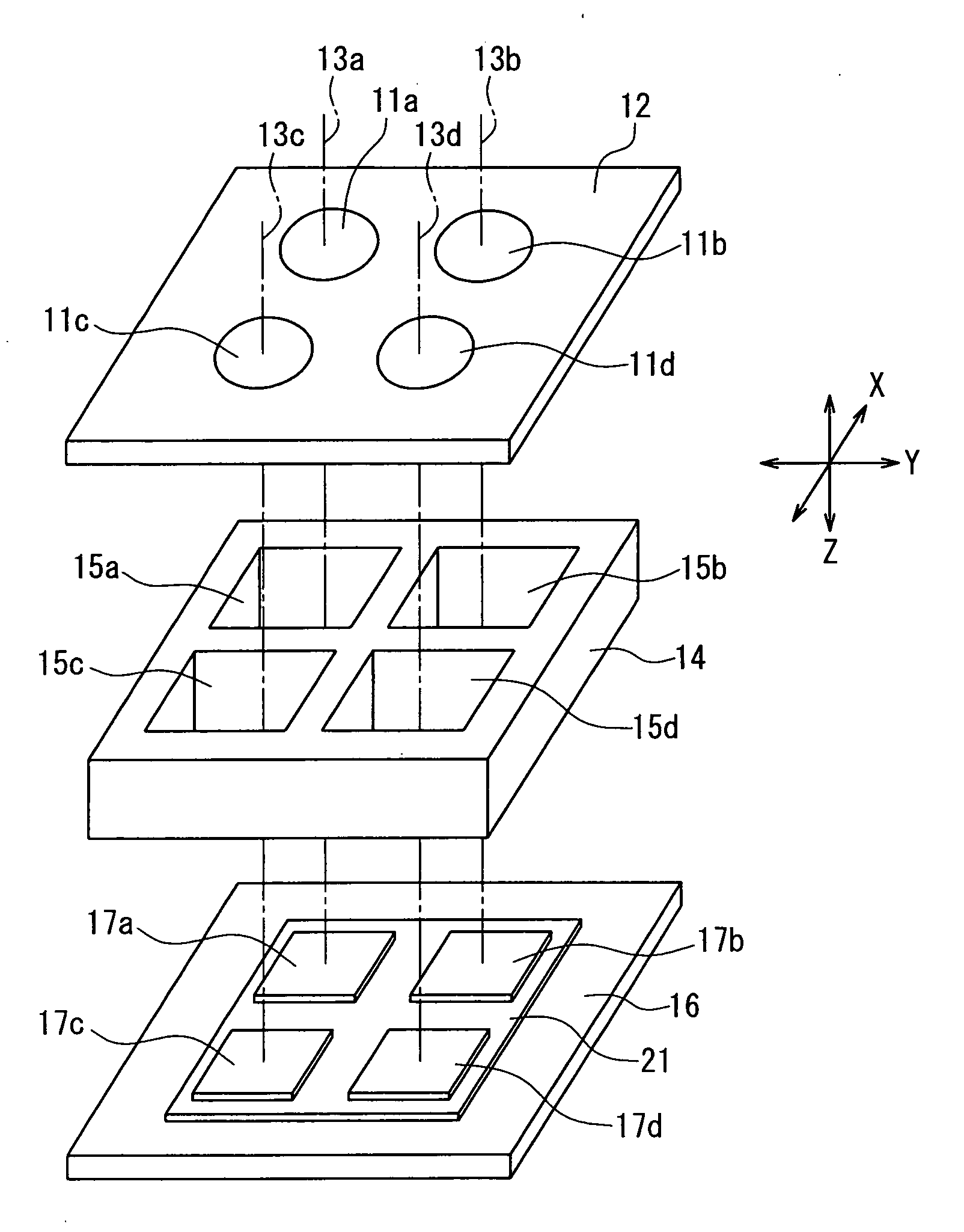
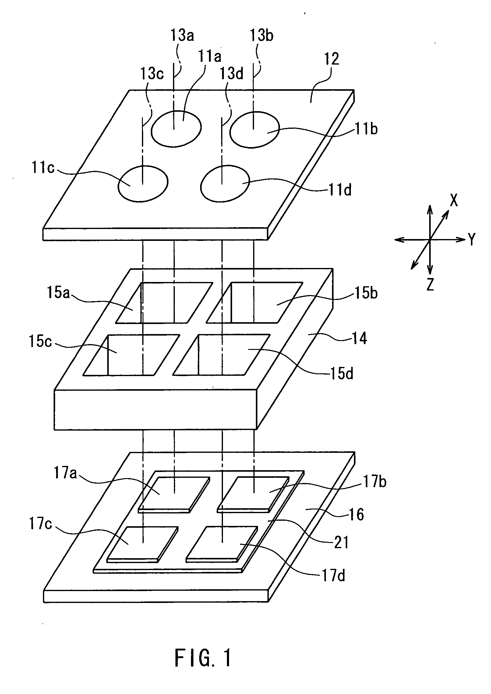
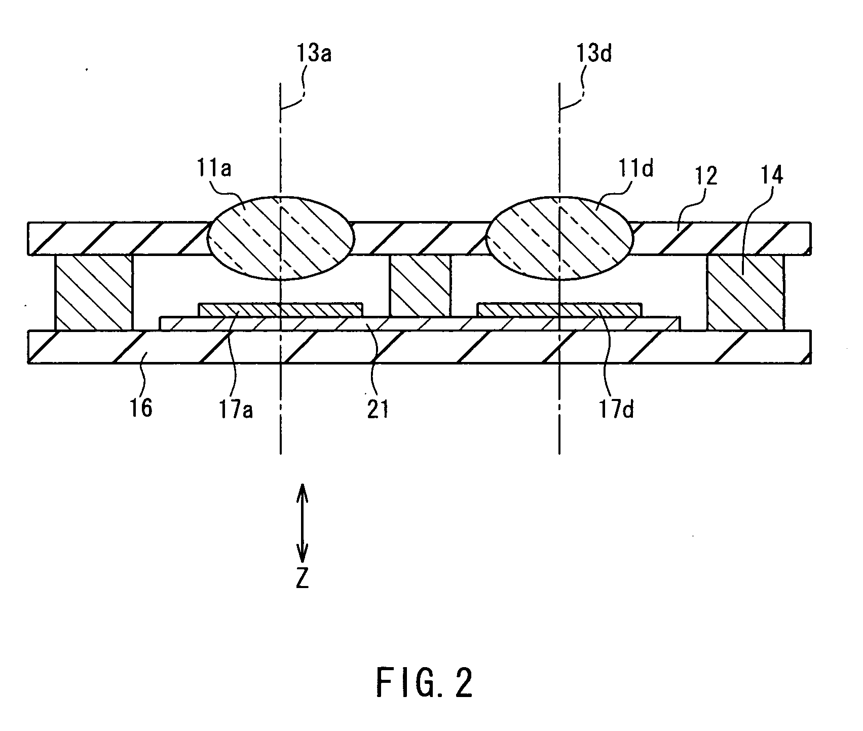
[0052]FIG. 1 is an exploded perspective view showing the schematic configuration of a camera module according to Embodiment 1 of the present invention. FIG. 2 is a cross-sectional view of the camera module according to Embodiment 1 taken along the optical axis.

[0053] Four lenses 11a, 11b, 11c and 11d are double-sided aspherical single lenses that are independent of one another, and are arranged and aligned by a lens holder 12 on a substantially common plane. Optical axes 13a, 13b, 13c and 13d of the four lenses 11a, 11b, 11c and 11d are each parallel to the normal of a principal plane of the lens holder 12. Herein, as shown in FIG. 1, it is assumed that the direction parallel to the optical axes 13a, 13b, 13c and 13d is the Z-axis, one direction perpendicular to the Z-axis is the X-axis and the direction perpendicular to the Z-axis and the X-axis is the Y-axis. The lenses 11a, 11b, 11c and 11d are arranged on a X-Y plane at lattice points formed with lines parallel to the X-axis an...

embodiment 2

[0090]FIG. 7 is an exploded perspective view showing the schematic configuration of a camera module according to Embodiment 2 of the present invention. FIG. 8 is a cross-sectional view of the camera module according to Embodiment 2 taken along the optical axis.

[0091] Four lenses 71a, 71b, 71c and 71d are aspherical single lenses with diffraction gratings on both sides. The lenses are independent of one another, and are arranged and aligned by a lens holder 72 on a substantially common plane. Optical axes 73a, 73b, 73c and 73d of the four lenses 71a, 71b, 71c and 71d are each parallel to the normal of a principal plane of the lens holder 72. Herein, as shown in FIG. 7, it is assumed that the direction parallel to the optical axes 73a, 73b, 73c and 73d is the Z-axis, one direction perpendicular to the Z-axis is the X-axis and the direction perpendicular to the Z-axis and the X-axis is the Y-axis. The lenses 71a, 71b, 71c and 71d are arranged on a X-Y plane at lattice points formed wi...

embodiment 3

[0102]FIG. 9 is a cross-sectional view of a camera module of the present embodiment taken along the plane including optical axes 73a and 73d. The camera module of the present embodiment is different from the camera module of Embodiment 2 of FIG. 8 in that an actuator 90 is added to shift an imaging device holder 75 relative to a lens holder 72 along the optical axis. The same reference numerals are assigned to the same elements of the camera module of Embodiment 2 and their explanations are not repeated.

[0103] The actuator 90 includes a piezoelectric element 91, a rod-shaped driving shaft 92 with the longitudinal direction thereof arranged parallel to the Z-axis, a pair of supporting blocks 93a and 93b opposed in the Z direction and a friction operation unit 94. One end of the piezoelectric element 91 is fixed to the supporting block 93a, and the other end is connected with one end of the driving shaft 92. The other end of the driving shaft 92 is fixed to the supporting block 93b. ...


PUM


Abstract

A plurality of single lenses (11a to 11d) form images of a subject in a plurality of imaging regions (17a to 17d), respectively, and electrical signals from the plurality of imaging regions are synthesized, whereby an image is obtained. The plurality of single lenses are held by a lens holder (12), and the plurality of imaging regions are held by an imaging device holder (16). The lens holder and the imaging device holder are disposed so as to be opposed to each other. The lens holder includes a member different from a member of the imaging device holder, and a linear expansion coefficient of a material of the lens holder is substantially equal to a linear expansion coefficient of a material of the imaging device holder. The materials of the lens holder and the imaging device holder are different from a material of the plurality of single lenses. Thereby, a high quality image can be obtained stably irrespective of a temperature change, and a distance to a subject can be measured accurately.

Description

TECHNICAL FIELD [0001] The present invention relates to a thin, compact and high-definition compound-eye type camera module capable of measuring a distance to a subject and having stable performance against an ambient temperature change. BACKGROUND ART [0002] Camera modules for forming an image of a subject on a solid-state imaging device via a lens system are used widely for digital still cameras and mobile phone cameras. In recent years, it has been required for camera modules to have a larger number of pixels in combination with a lower profile. In general, as the number of pixels is increased, a lens system is required to have a higher resolution, and therefore the thickness of a camera module tends to increase in the optical axis direction. In this regard, an attempt has been made to reduce the pixel pitch of a solid-state imaging device so as to reduce the imaging device in size while keeping the same number of pixels, in order to enable the downsizing of a lens system and rea...

Claims


Application Information

Patent Timeline
IPC IPC(8): G02B13/16
CPCG02B5/003G02B5/1876H04N3/1593H04N5/2254H04N23/55H04N25/41
Inventor KORENAGA, TSUGUHIRO
Owner PANASONIC CORP
Why Eureka
Try Eureka