Liquid crystal display device

a liquid crystal display and display device technology, applied in the field of display devices, can solve the problems of difficult separation of first frame and second frame and achieve the effect of improving the structure strength and improving the lodge strength of the liquid crystal display devi

Inactive Publication Date: 2007-05-03
CHUNGHWA PICTURE TUBES LTD
View PDF10 Cites 16 Cited by
  • Summary
  • Abstract
  • Description
  • Claims
  • Application Information

AI Technical Summary

Benefits of technology

[0021] In summary, the liquid crystal display device of the present invention utilizes the baffles lodged in the fasteners to improve the lodge strength between frames and then the structure strength of the liquid crystal display device can be improved, too.

Problems solved by technology

When the liquid crystal display device is impacted, a first frame and a second frame of the liquid crystal display device can not be separated easily.

Method used


Image

  • Liquid crystal display device
  • Liquid crystal display device
  • Liquid crystal display device

Examples


first embodiment

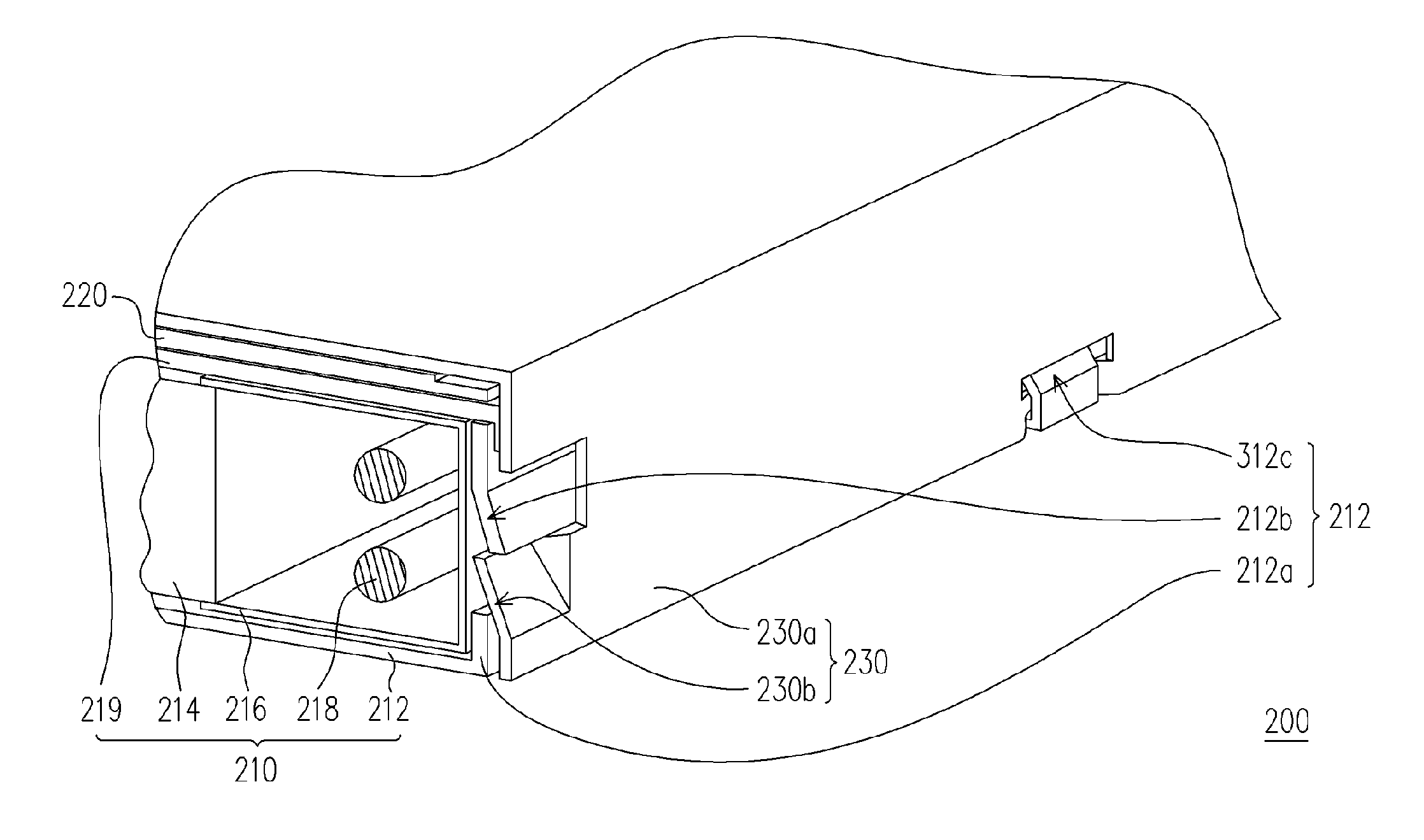
[0036]FIG. 3 is a three-dimensional diagram showing a liquid crystal display device according to the first embodiment of the present invention. Please refer to FIG. 3, the liquid crystal display device 200 comprises a backlight module 210, a liquid crystal display device panel 220 and a second frame 230. The backlight module 210 comprises a first frame 212. The liquid crystal display device panel 220 is arranged on the backlight module 210. The first frame 212 is assembled with the second frame 230, to fix the liquid crystal display device panel 220. Besides, the backlight module 210 further comprises a light guiding plate 214, a reflector 216, a light source 218 and a sealant 219. The light guiding plate 214 is arranged inside the first frame 212. The reflector 216 is arranged beside the light guiding plate 214. The light source 218 is arranged inside the reflector 216. The sealant 219 is arranged between the first frame 212 and the liquid crystal display device panel 220. The ligh...

second embodiment

[0038]FIG. 5A is a three-dimensional diagram of the assembled frames according to a second embodiment of the present invention, and FIG. 5B is a three-dimensional diagram of the baffle shown in FIG. 5A. Please refer to FIGS. 5A and 5B, the liquid crystal display device 300 of the second embodiment is similar to the liquid crystal display device 200 of the first embodiment, the difference between them is that the baffles 312c used in this embodiment pierce through the second body 230a, and the baffle 312c and the first body 212a are disposed at one side and the other side of the sidewall of the second body 230a respectively.

[0039]FIG. 5C is a schematic cross-sectional view showing the first fastener when against the impact according to the second embodiment. Compared with the baffles 212c shown in FIG. 3, the baffle 312c may further extend and pierce through the inner side of the first body 230a of the second frame 230. More specifically, the baffle 312c and the first body 212a are ...

third embodiment

[0040]FIG. 6A is a partial three-dimensional diagram of the assembled frames according to a third embodiment of the present invention. FIG. 6B is a three-dimensional diagram of the baffle shown in FIG. 6A. Please refer to FIGS. 6A and 6B, the liquid crystal display device of the third embodiment is similar to the liquid crystal display device 200 of the first embodiment, the difference between them is that: the first fastener 312b of the first frame 212 comprises an opening 312d (as shown in the left hand side of FIG. 6B), such that a portion of the corresponding second fastener 230b can lodge in the opening 312d. It should be noted that, in this embodiment, the first fastener 312b further extends and pierces through the inner side of the second body 230a (similar to the baffle 312c of the second embodiment).

[0041]FIG. 6C is a schematic cross-sectional view showing the first fastener when against the impact according to the third embodiment. Please refer to FIG. 6C, the first faste...


PUM

PropertyMeasurementUnit
relative displacementaaaaaaaaaa
impact forceaaaaaaaaaa
structure strengthaaaaaaaaaa

Abstract

A liquid crystal display device including a backlight module, a liquid crystal display device panel and a second frame is provided. The backlight module includes a first frame. The first frame includes a first body, first fasteners and baffles. The first fasteners and the baffles are arranged on a sidewall of the first body. The liquid crystal display device panel is arranged on the backlight module. The second frame is assembled with the first frame for fixing the liquid crystal display device panel, and includes a second body and second fasteners arranged on a sidewall of the second body. The first fasteners fasten with the corresponding second fasteners, to limit the relative displacement between the first and second body along a first direction, and the baffles are adapted for limiting the relative displacement between the first and second body along a second direction.

Description

BACKGROUND OF THE INVENTION [0001] 1. Field of the Invention [0002] The present invention generally relates to a display device. More particularly, the present invention relates to a liquid crystal display device. [0003] 2. Description of Related Art [0004] Recently, the thin film transistor liquid crystal display device (TFT-LCD) having the advantages of high picture quality, slim, low power consumption and radiation-free has gradually become the mainstream in the display market. The TFT-LCD is composed of a liquid crystal display device panel and a backlight module. The liquid crystal display device panel and the backlight module are assembled by frames. [0005]FIG. 1 is a schematic cross-sectional view showing a conventional liquid crystal display device. The conventional liquid crystal display device 100 comprises a backlight module 110, a liquid crystal display device panel 120 and a second frame 130. The backlight module 110 comprises a first frame 112. The liquid crystal displ...

Claims


Application Information

Patent Timeline
Patent Type & Authority Applications(United States)
IPC IPC(8): G02F1/1333
CPCG02B6/0081G02F1/133308G02F1/133615G02F2001/133322G02F2201/465G02F1/133322
Inventor HO, CHUNG-HSINGWANG, YAO-TUNG
Owner CHUNGHWA PICTURE TUBES LTD
Why Eureka
Try Eureka