Printing apparatus, print instruction apparatus, and printing system

a printing system and instruction apparatus technology, applied in the direction of digital output to print units, instruments, computing, etc., can solve the problems of difficult significant cost increase, and general non-standardization of pbr methods, so as to prevent the occurrence of overhead, efficient use of print buffers, and efficient and effective use of system resources

Inactive Publication Date: 2007-05-03
PANASONIC CORP
View PDF8 Cites 30 Cited by
  • Summary
  • Abstract
  • Description
  • Claims
  • Application Information

AI Technical Summary

Benefits of technology

[0065] As apparent from the above description, in the printing apparatus, the print instruction apparatus, and the printing system according to the present invention, only when the print data is no longer obtained again, the print data can be promptly deleted from the print buffer. Therefore, it is possible to completely prevent from the occurrence of the overhead and from the too long keeping of the print data, and at the same time able to efficiently use the print buffer.
[0066] Therefore, according to the present invention, a printing system using the pull method, in which an efficient and effective use of the system resources can be realized among apparatuses having little hardware resources, can be realized, so that the present invention is highly suitable for practical use, in recent days the Internet has been widely used.
[0067] The present invention will become apparent from the following embodiments and the accompanying drawings, but the embodiments nor the drawings are provided only as specific examples, and the present invention is not limited to the embodiments nor the drawings.

Problems solved by technology

For an inexpensive host, it is difficult to have the Internet connection function which results in significant cost increase, but even such a host can realize a print function for data on the Internet, so that the PBR method is expected to be widely used in the future.
Note that the PBR method generally does not standardize a timing of deleting print data on the Web server.
If the print data needs to be kept until the completion of printing output, for a long time the host apparatus cannot release a print data buffer (work memory such as a RAM) for storing the print data, so that an efficient and effective use of system resources becomes difficult.

Method used


Image

  • Printing apparatus, print instruction apparatus, and printing system
  • Printing apparatus, print instruction apparatus, and printing system
  • Printing apparatus, print instruction apparatus, and printing system

Examples


first embodiment

[0140]FIG. 5 is a block diagram showing a whole configuration of a printing system according to the first embodiment of the present invention.

[0141] As shown in FIG. 5, a printing system 1 includes: a document image supplying apparatus 1100; an image forming apparatus 1200; and a transmission medium 1300 which connects the document image supplying apparatus 1100 with the image forming apparatus 1200 so that the document image supplying apparatus 1100 and the image forming apparatus 1200 can communicate with each other.

[0142] As the document image supplying apparatus 1100, a digital television set, a set-top box (STB), and the like can be used, and moreover, any other apparatuses which serve as sources of data can be also applied. Note also that, as the image forming apparatus 1200, a printer, a facsimile, or the like can be used. Note also that, as the transmission medium 1300, mediums used between a computer and a printer, such as a bus, a public network, a dedicated line, an Int...

second embodiment

[0188] Next, a printing system according to the second embodiment of the present invention is described. Note that configuration of this printing system is the same as the configuration of the printing system 1 shown in FIG. 5 in the first embodiment, so that the configuration of this system is not shown in the drawings.

[0189] In the meantime, in the above-described first embodiment, it has been described as an example that the print document 1400 shown in FIG. 6, namely, an identical object, is used twice, but in a printing system using the pull method, a print document 1500 shown in FIG. 12 may be used.

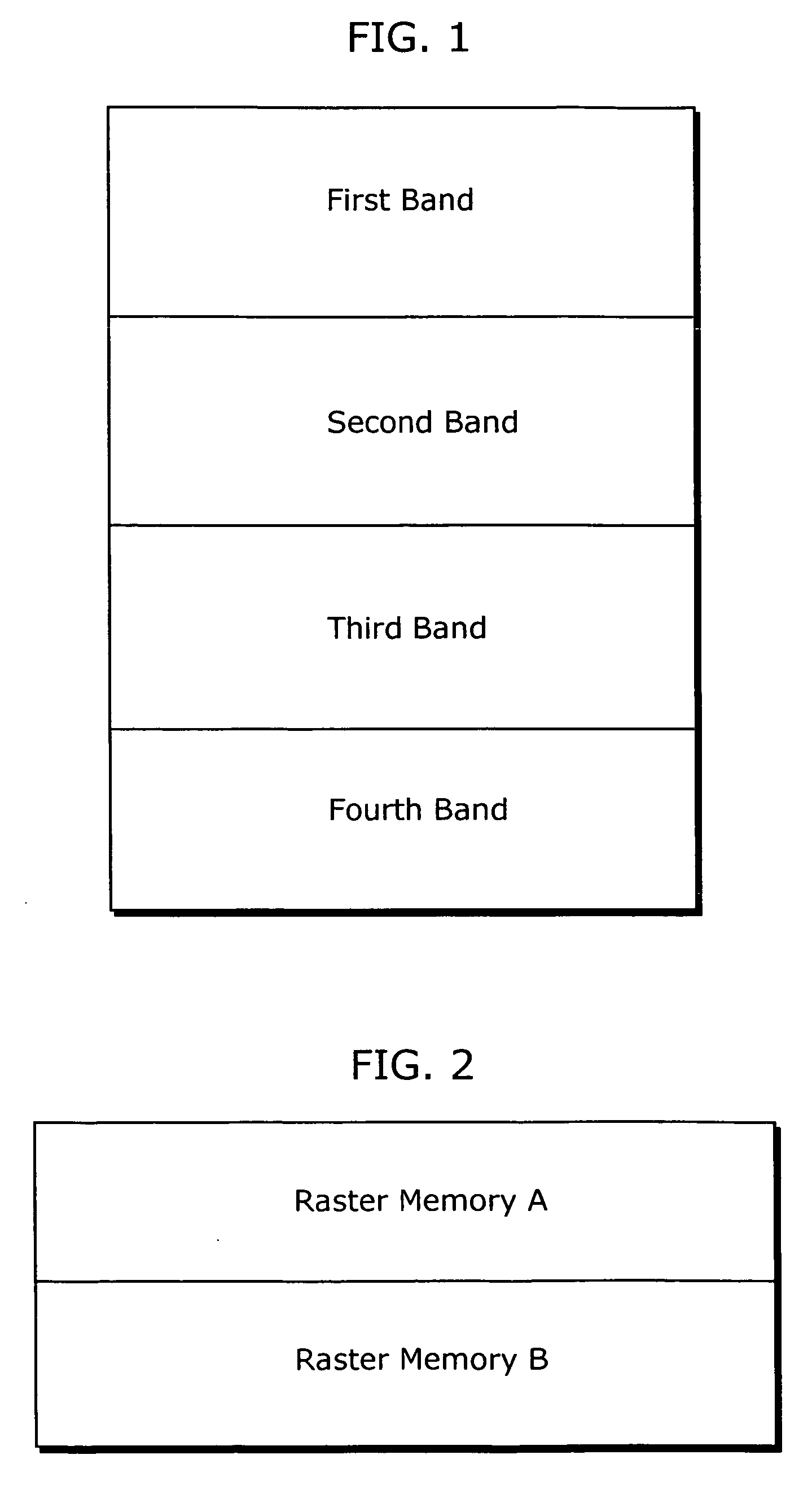
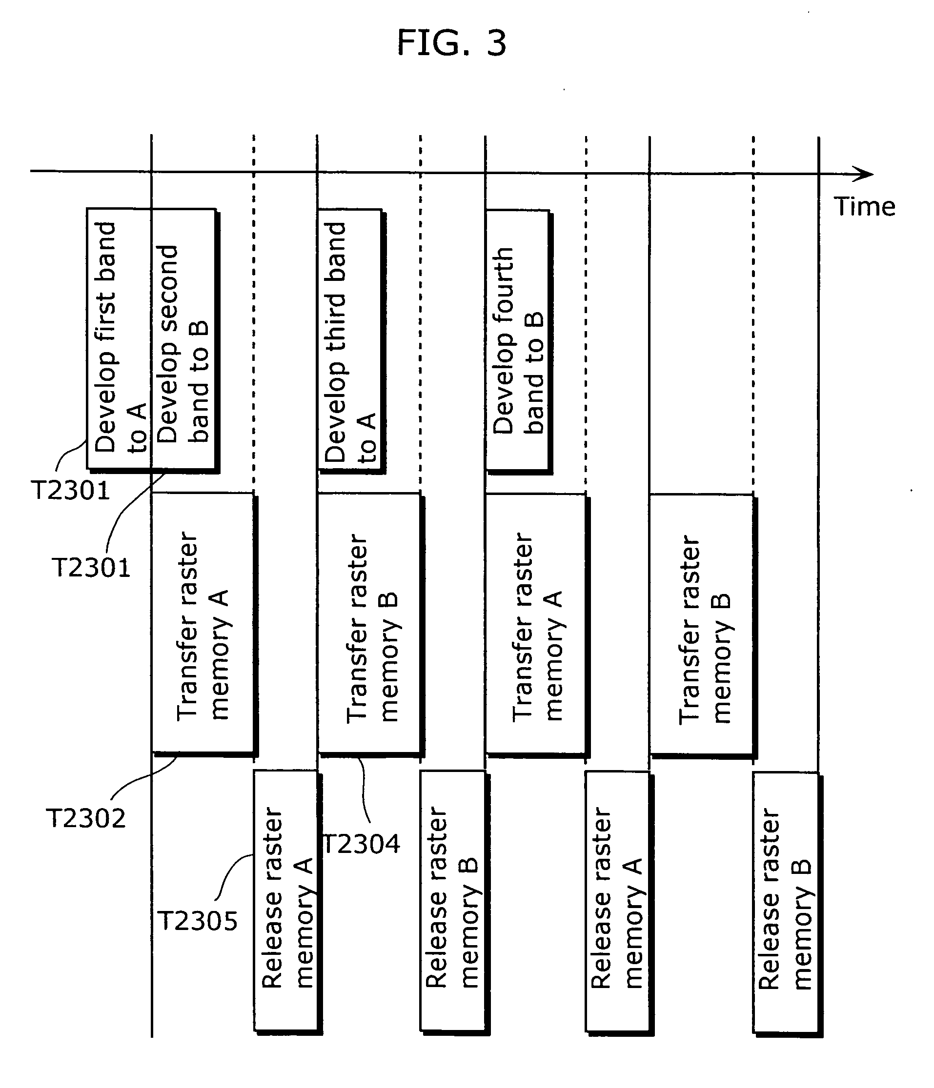
[0190] The print document 1500 of FIG. 12 includes a print description data and a single image object 1501, and depending on a memory capacity of the print buffer 1105, it is necessary, as shown in FIG. 13, to divide the image object 1501 into image objects 1511 to 1513 for example, and to sequentially store the image objects 1511 to 1513 into the print buffer 1105 firstly from an...

third embodiment

[0200] Next, a printing system according to the third embodiment of the present invention is described.

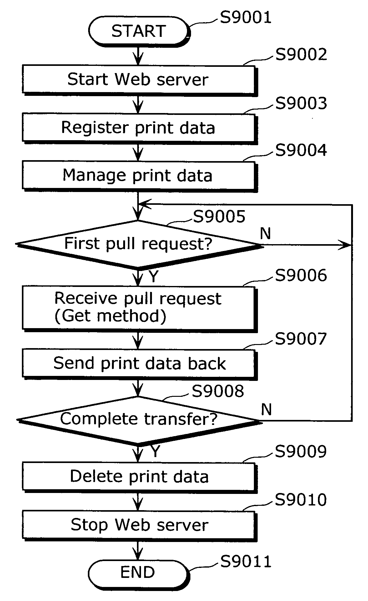
[0201]FIG. 18 is a diagram showing a whole configuration of a printing system according to the third embodiment of the present invention. The printing system 2, as shown in FIG. 18, includes: a host apparatus 2001; a printing apparatus 2002; and a network 2003 which connects the host apparatus 2001 and the printing apparatus 2002. Here, the present invention relates to communication and management of print data, so that FIG. 18 also shows locations of communication functions.

[0202] The host apparatus 2001 includes a PBR client function 2004 and a Web server function 2007.

[0203] The printing apparatus 2002 includes a PBR device function 2005 and a Web client function 2006.

[0204] The PBR client function 2004 provides a client communication function using the Print-by-Reference (PBR) method. The PBR device function 2005 provides a device side communication functions for PBR printi...


PUM


Abstract

Provided is a printing apparatus which receives a print instruction, then obtains and prints print data including plural pieces of sub-data, and
    • the printing apparatus includes: a print data obtainment unit (interpreter 1203) which obtains the sub-data; a determination unit (rasterizer 1202) which determines whether or not there is necessity of further obtaining of the obtained sub-data, by the interpreter 1203, in order to complete printing of the print data; and a notification unit (communication I/F 1204) which notifies a result of the determination, to a print instruction apparatus which issues the print instruction, when the determination is made that there is no necessity.

Description

TECHNICAL FIELD [0001] The present invention relates to a printing apparatus, a print instruction apparatus, and a printing system, and more particularly to a memory release control technology for a print buffer which stores print data temporarily. BACKGROUND ART [0002] Conventionally, regarding printing systems connected via a network, in a printing system using a Pull method, by which a printing apparatus (hereinafter, referred to also as “image forming device” or “printer”) requests a print instruction apparatus (hereinafter, referred to also as “document image supplying apparatus”, or “host apparatus”) to transfer print data, the print data is accumulated into a print buffer included in the document image supplying apparatus, then during printing performed by the image forming apparatus, necessary print data is requested, every time the print data becomes necessary, to be transferred from the document image supplying apparatus, and eventually the necessary print data is received...

Claims


Application Information

Patent Timeline
Patent Type & Authority Applications(United States)
IPC IPC(8): G06F3/12
CPCG06F3/1285G06F3/12
Inventor HIGASHIMURA, TAKAHIROYAMAGUCHI, TAKEHITOMATSUNAGA, SHIGEKI
Owner PANASONIC CORP
Why Eureka
Try Eureka