Marker and method for detecting said marker

a technology of visual markers and markers, applied in the field of visual markers and methods of detecting visual markers, can solve the problems of not always very effective, existing fiducial marker systems such as artoolkit, artoolkit plus, binary square markers, etc., and achieve the effect of more robustness

Active Publication Date: 2007-05-03
MILLENNIUM THREE TECH
View PDF6 Cites 141 Cited by
  • Summary
  • Abstract
  • Description
  • Claims
  • Application Information

AI Technical Summary

Problems solved by technology

These are not always very effective because of their reliance on the lighting conditions and specific light gathering device used, for example systems relying on recognizing color in markers typically need more expensive video cameras, need to control the lighting so the spectral content and brightness does not vary, and often need to not change the cameras or their positions.
Existing fiducial marker systems such as ARToolkit, ARToolkit Plus, Matrix, Binary Square Marker, cybercode suffer from this susceptibility to lighting.
This susceptibility is due to the binary thresholding algorithm used by these and other marker systems, the weakness lies in their common approach of attempting to label all image pixels as belonging to one or another set, these systems attempt to classify parts of the image by some method to attempt to recognize different levels of reflectance from the marker and its surroundings.
This often fails because it is often not possible to separate objects or marker sections by applying a brightness or color threshold.
These systems do not function well because of the assumption that parts of markers with equal reflectance properties (shading or coloring) will manifest themselves as regions of uniform incoming light to an image sensor.
Often marker systems fail in the first step due to their reliance on the binarization method described above.
Another source of weakness for existing marker systems is their lack of robust processing in the verification and identification stages.
Some use checksums such as Matrix and Binary Square Marker which gives them more robust performance, but these systems still fall short of practical usability because of their use of the binarization method, and because of an insufficient amount of information in the marker.
Binary Square marker only uses a grid of 12 information carrying cells in the marker which cannot convey much information to allow reliable detection.
The act of extracting a set of digital symbols from the image sensor's array of pixels can sometimes introduce errors due to sources such as image sensor noise, lighting variances, or partial occlusion (blocking) of objects.
Current marker systems do not use both error correction and checksums which greatly reduces their effectiveness.
2D barcode systems such as Datamatrix, QR, Maxicode and Cybercode (FIG. 1) are not suitable as fiducial markers because they provide less than four such salient points.
Finally, existing systems that use digital patterns do not provide proper level of information encoded in the marker.
The existing systems only typically exist in laboratories due to their weakness in some or all of the above categories, their lack of robustness discounts them from wide implementation in industry and society.

Method used


Image

  • Marker and method for detecting said marker
  • Marker and method for detecting said marker
  • Marker and method for detecting said marker

Examples


Embodiment Construction

[0043] Other advantages that are inherent to the structure are obvious to one skilled in the art. The embodiments are described herein illustratively and are not meant to limit the scope of the invention as claimed. Variations of the foregoing embodiments will be evident to a person of ordinary skill and are intended by the inventor to be encompassed by the following claims.

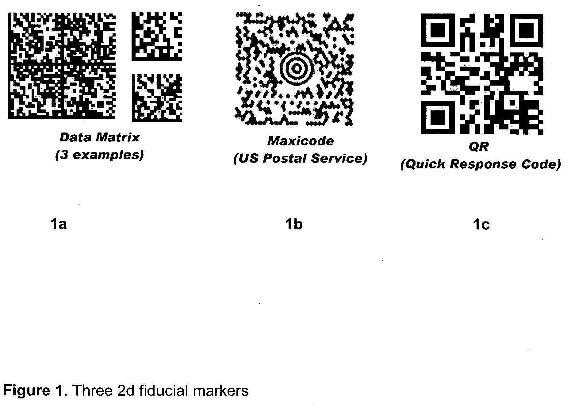
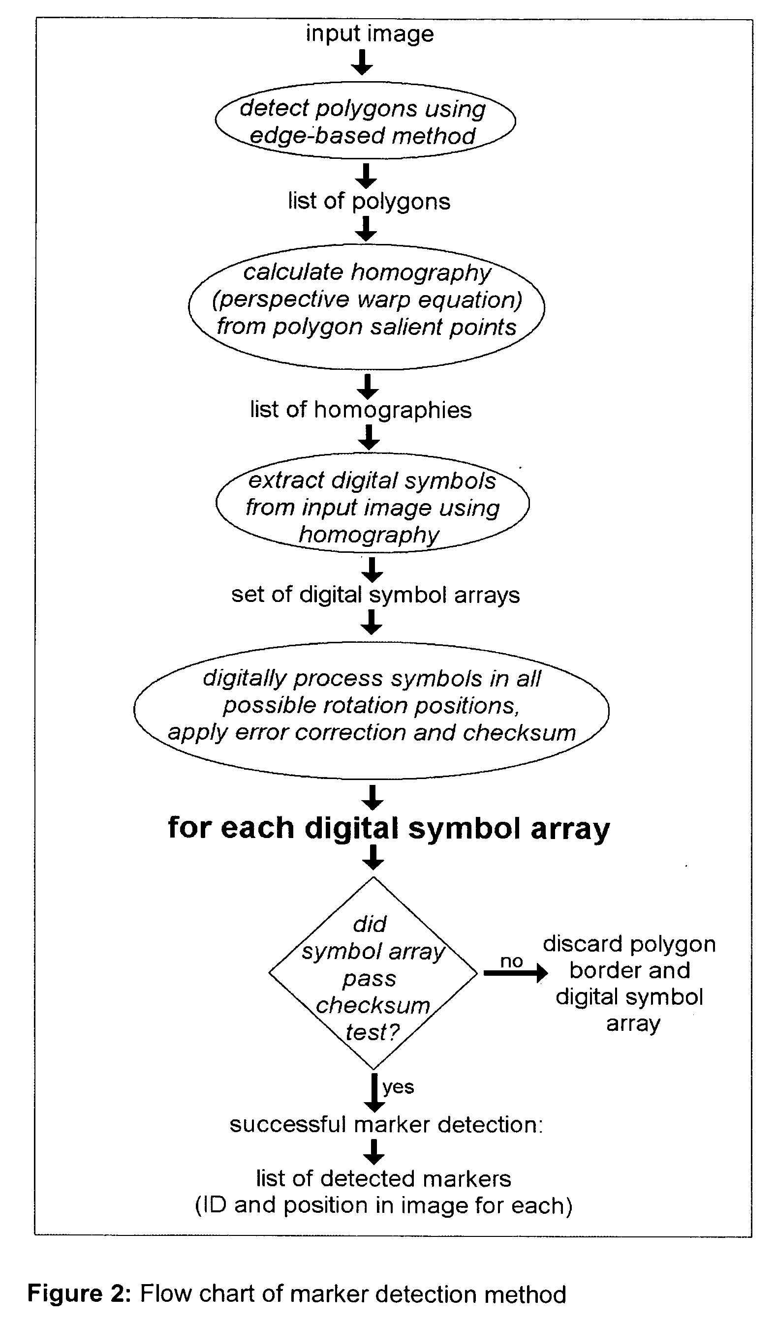
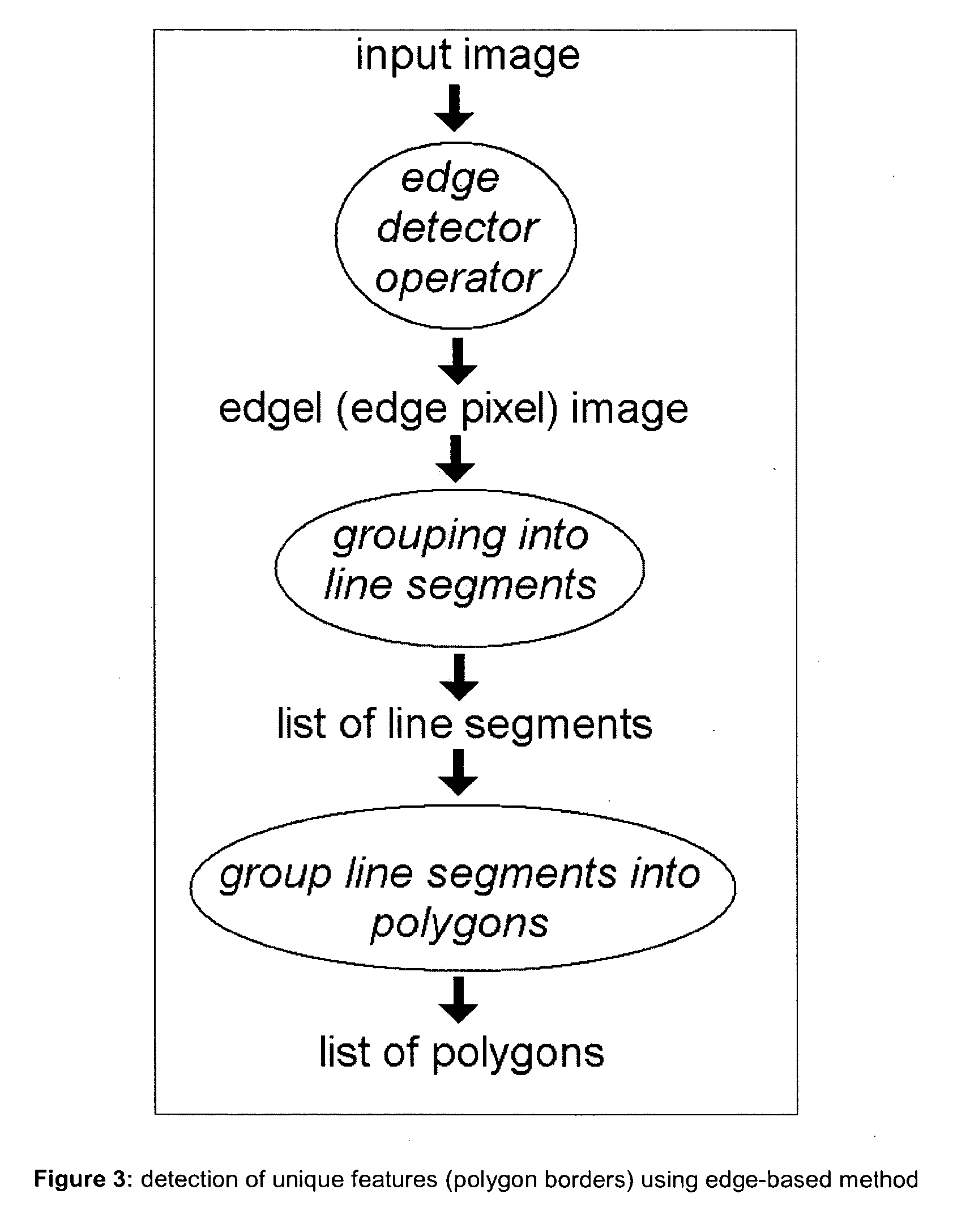
[0044] This application describes a “fiducial marker system” using digital patterns designed to satisfy the requirements stated in the background section. It includes the simultaneous application of an edge-based method to find polygon borders and the use of single or multi level of data including both checksums and error correction in the digital pattern component of the marker. The edge-based approach for polygon border detection provides more robust detection of markers in situations of uncontrolled lighting and partial occlusion. The dual level marker allows for additional information to be stored, including...


PUM


Abstract

This invention discloses marker detectable by visual means comprising; a polygonal border having of at least four non collinear salient points. The marker has on it a pattern in binary digital code. The binary code data contains information data, checksum and error correction. The binary code data is on two levels; a first level of binary code readable at a first given distance, a second level of binary code readable at a second given distance, where the second given distance is less than the first given distance and the second level binary code is smaller in size than the first level binary code. The second level of binary code does not interfere with the reading of the first level binary code. It also discloses a method for detecting a marker comprising the steps of detecting an image, using an edge detector to detect an edge in said image, grouping more than one edge into a polygon having salient points, calculating homography from polygon salient points, generating a list of homographies, extracting binary data from input image having homographies, identifying and verifying binary data.

Description

[0001] This application is a cross-reference of corresponding U.S. Provisional Patent Application 60 / 731,478 filed Oct. 31, 2005. Field of the Invention [0002] This invention relates to visual markers and methods of detecting visual markers. More specifically, this invention relates to markers used in Augmented reality and 3D position sensors. BACKGROUND OF THE INVENTION [0003] Marker patterns can be added to objects or scenes to allow automatic systems to find correspondence between points in the world and points in camera images, and to find correspondences between points in one camera image and points in another camera image. The former has application in positioning, robotics, and augmented reality applications, the latter has application in automatic computer modeling to provide the coordinates of world points for applications of the former. Furthermore, marker patterns can be used to contain information relating to various products. For example, marker patterns printed out and...

Claims


Application Information

Patent Timeline
Patent Type & Authority Applications(United States)
IPC IPC(8): G06T7/00
CPCG06K9/3216G06K2009/3225G06T7/0042G06T7/0083G06T2207/10016G06T2207/30208H03M13/09G06T7/73G06T7/12G06V10/245
Inventor FIALA, MARK
Owner MILLENNIUM THREE TECH
Why Eureka
Try Eureka