Method and system for stabilizing operation of laser sources

a laser source and laser technology, applied in the direction of electromagnetic transmission, semiconductor lasers, electromagnetic transmission, etc., can solve the problems of inability to compensate aging effects, add to the circuital complexity of the system, and undetectable interference with transmitted data and/or other tones

Active Publication Date: 2007-05-03
WISTRON CORP
View PDF6 Cites 18 Cited by
  • Summary
  • Abstract
  • Description
  • Claims
  • Application Information

AI Technical Summary

Benefits of technology

[0005] The need is therefore felt for arrangements that permit the optical eye-shape (average power and ER) to be maintained against temperature fluctuations and laser aging without requiring characterization over temperature during the laser module set-up and, preferably, without requiring additional circuitry.
[0013] An embodiment of the invention permits the optical eye-shape to be maintained against temperature fluctuations and laser aging without a characterisation over temperature during module set-up. Additionally, the present embodiment of the invention relies on a specific algorithm implemented in a micro-controller to properly set modulation and bias current amplitudes without requiring any additional specific circuit.

Problems solved by technology

These prior art arrangements require characterization of the behaviour of the laser source against temperature for modulation control and are generally unable to compensate aging effects.
These arrangements add to the circuital complexity of the system, and the pilot tone present in the optical power may undesirably interfere with transmitted data and / or other tones.

Method used


Image

  • Method and system for stabilizing operation of laser sources
  • Method and system for stabilizing operation of laser sources
  • Method and system for stabilizing operation of laser sources

Examples


Embodiment Construction

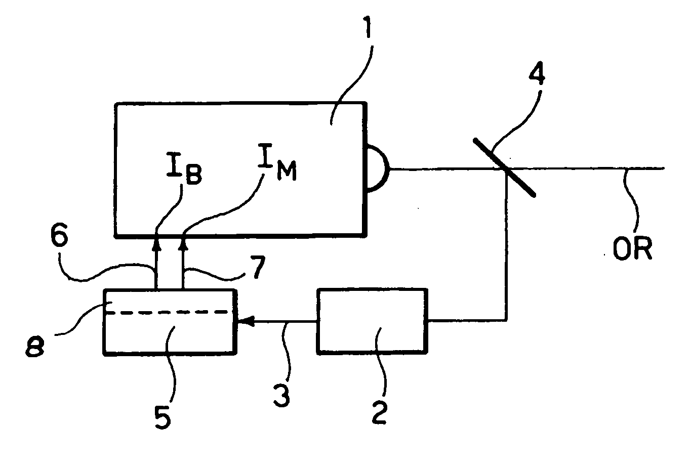
[0018] In FIG. 1, reference 1 denotes a laser source of any known type (e.g. DFB) as currently used in laser optical communications. The laser source 1 has an associated power sensing module 2 adapted to produce over an output line 3 a signal representative of the power of the optical radiation OR as emitted by the laser source 1. For that purpose, a semi-reflective mirror 4 is interposed in the path of the radiation OR to “split” a (very small) portion of that radiation and direct it into the sensing module 2. This typically includes an opto-electrical converter (such as a photodiode or phototransistor) that converts the optical radiation fed into the module 2 into a corresponding electrical signal.

[0019] Sensing arrangements as just described are common in the art as used e.g. in so-called “wavelength-locker” arrangements. These include a wavelength-sensitive module adapted to sense any variation in the wavelength of the radiation emitted by the laser source and feed a wavelength...


PUM


Abstract

A system for stabilizing an output optical power from a laser source against drifts induced by temperature and / or aging, said output optical power including a target optical modulation amplitude around a target average value includes: a power sensor for sensing the output optical power from the laser source and generating a power sensing signal indicative thereof, and a controller sensitive to the power sensing signal and configured for selectively adjusting the bias (IB) and modulation (IM) currents of the laser source by: detecting an error between the actual average output optical power from the laser source and the target average value,comparing the error against a given error threshold, and when the error reaches the threshold adjusting the bias (IB) and modulation (IM) currents to bring the output optical power from the laser source (1) back to the target average value (Ptarget) and the target optical modulation amplitude (OMAtarget) around the target average value (Ptarget).

Description

FIELD OF THE INVENTION [0001] The invention relates to techniques for stabilizing operation of laser sources such as those used e.g. in optical fiber communication links. DESCRIPTION OF THE RELATED ART [0002] In laser optical communication links, the need arises of stabilizing against temperature and aging the so-called “eye-shape”. This designation currently indicates the pattern obtained by displaying on an oscilloscope screen the traces generated by the “0s” and “is” comprising a data flow transmitted over the link. In general terms, an eye-shape “wide open” corresponds to optimum performance of the transmitter. [0003] Prior art arrangements exists that counter the negative effects of temperature on the eye-shape (average power and Extinction Ratio ER) by resorting to Automatic Power Control (APC) circuitry or optical power stabilization. These prior art arrangements require characterization of the behaviour of the laser source against temperature for modulation control and are g...

Claims


Application Information

Patent Timeline
Patent Type & Authority Applications(United States)
IPC IPC(8): H04B10/04H01S5/06H01S5/0683
CPCH01S5/0617H01S5/06832H01S3/131
Inventor LUPO, SILVIOAZZINI, GLUSEPPE ACHILLEFORNERO, GLUSEPPE
Owner WISTRON CORP
Why Eureka
Try Eureka