
Developing device and image forming apparatus

a technology of developing device and image forming apparatus, which is applied in the direction of electrographic process apparatus, instruments, optics, etc., can solve the problems of inconvenient high-frequency noise, inconsistency in density, and image defect, and achieve the effect of efficiently reducing noise and reducing nois

Inactive Publication Date: 2007-05-03
CANON KK
View PDF3 Cites 8 Cited by
  • Summary
  • Abstract
  • Description
  • Claims
  • Application Information

AI Technical Summary

Benefits of technology

[0017] The present invention is directed to a developing device and an image forming apparatus that are capable of efficiently reducing noise produced by the application of an alternating-current bias applied to a developer carrier. The present invention is also directed to a developing device and an image forming apparatus that are capable of efficiently reducing noise produced by the application of an alternating-current bias applied to a developer carrier when the frequency of the alternating-current bias is changed.
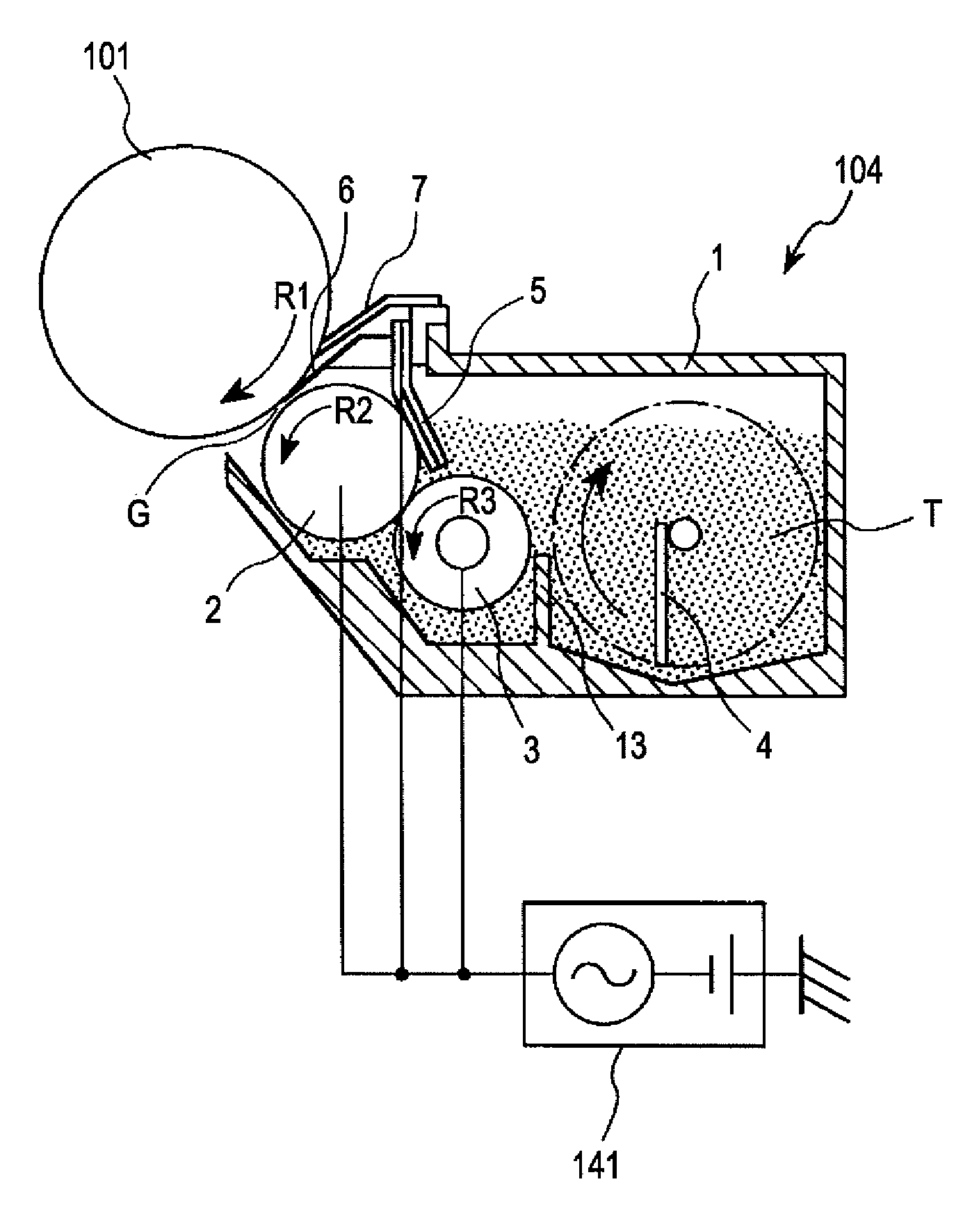
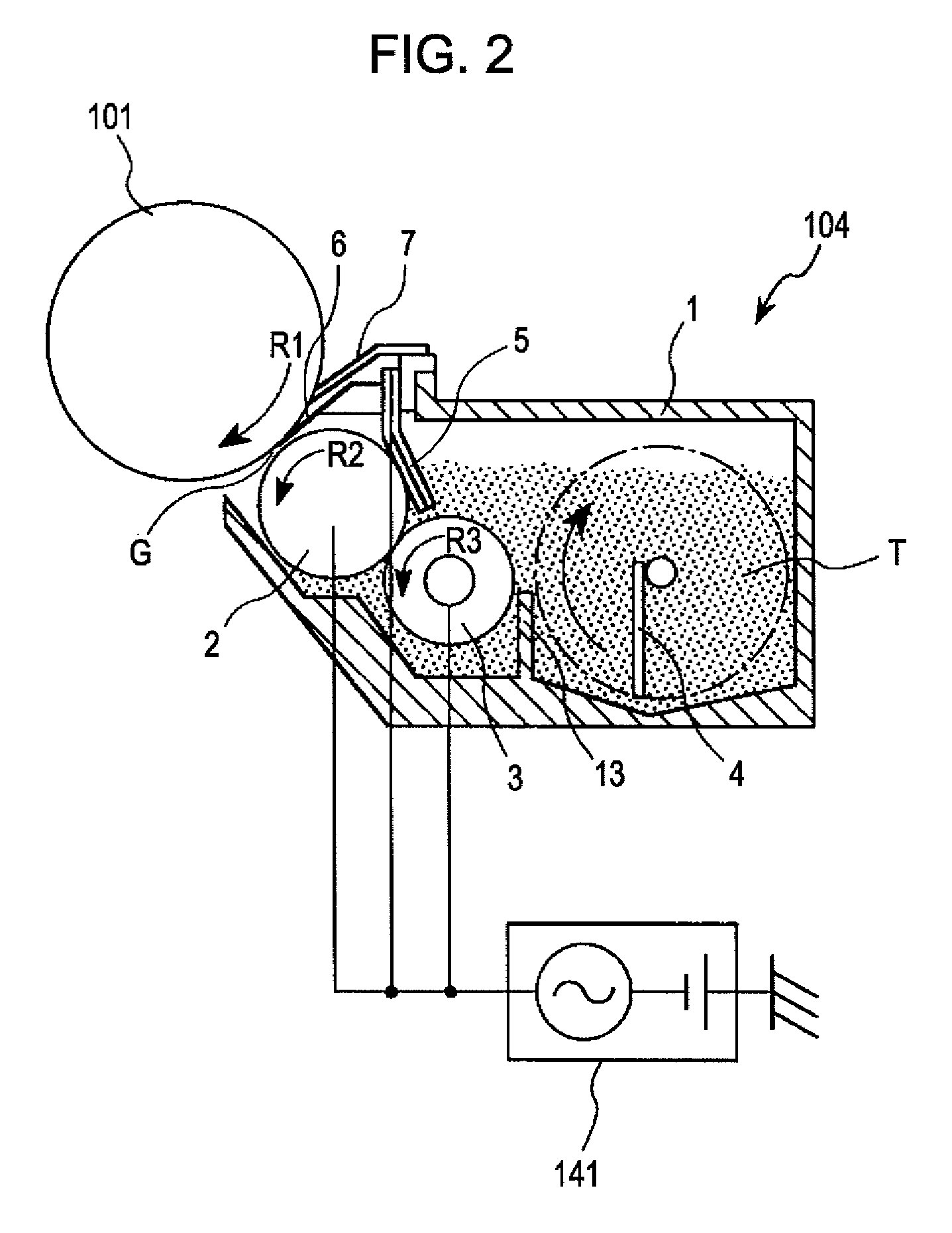
[0018] According to a first aspect of the present invention, a developing device for developing an electrostatic image formed on an image carrier with developer includes a developer carrier configured to carry and convey the developer. The device also includes a developer flying regulation member including a first end disposed between the image carrier and the developer carrier and being configured to regulate an area where the developer flies, and a development-noise regulation member covering the developer flying regulation member. The developing device develops an electrostatic image formed on the image carrier by causing the developer to fly from the developer carrier to the image carrier upon an application of an alternating-current bias to the developer carrier. In the developing device, noise produced by the development-noise regulation member vibrated by an oscillating electric field of the alternating-current bias is smaller than a noise produced by the developer flying regulation member vibrated by the oscillating electric field.

Problems solved by technology

The toner image like this causes an image defect of inconsistencies in density in that one area is denser than the other areas.
This may cause the plate member to resonate with the AC electric field and thus increase the vibration of the plate member, so that an unpleasant high-frequency noise (hereinafter referred to as “AC noise” or “development noise”) may be produced.
However, the coincidence between the natural frequency of the plate member and the frequency of the AC bias may cause resonance of the plate member and produce noise.

Method used


Image

  • Developing device and image forming apparatus
  • Developing device and image forming apparatus
  • Developing device and image forming apparatus

Examples


first exemplary embodiment

[General Structure and Operation of Image Forming Apparatus]

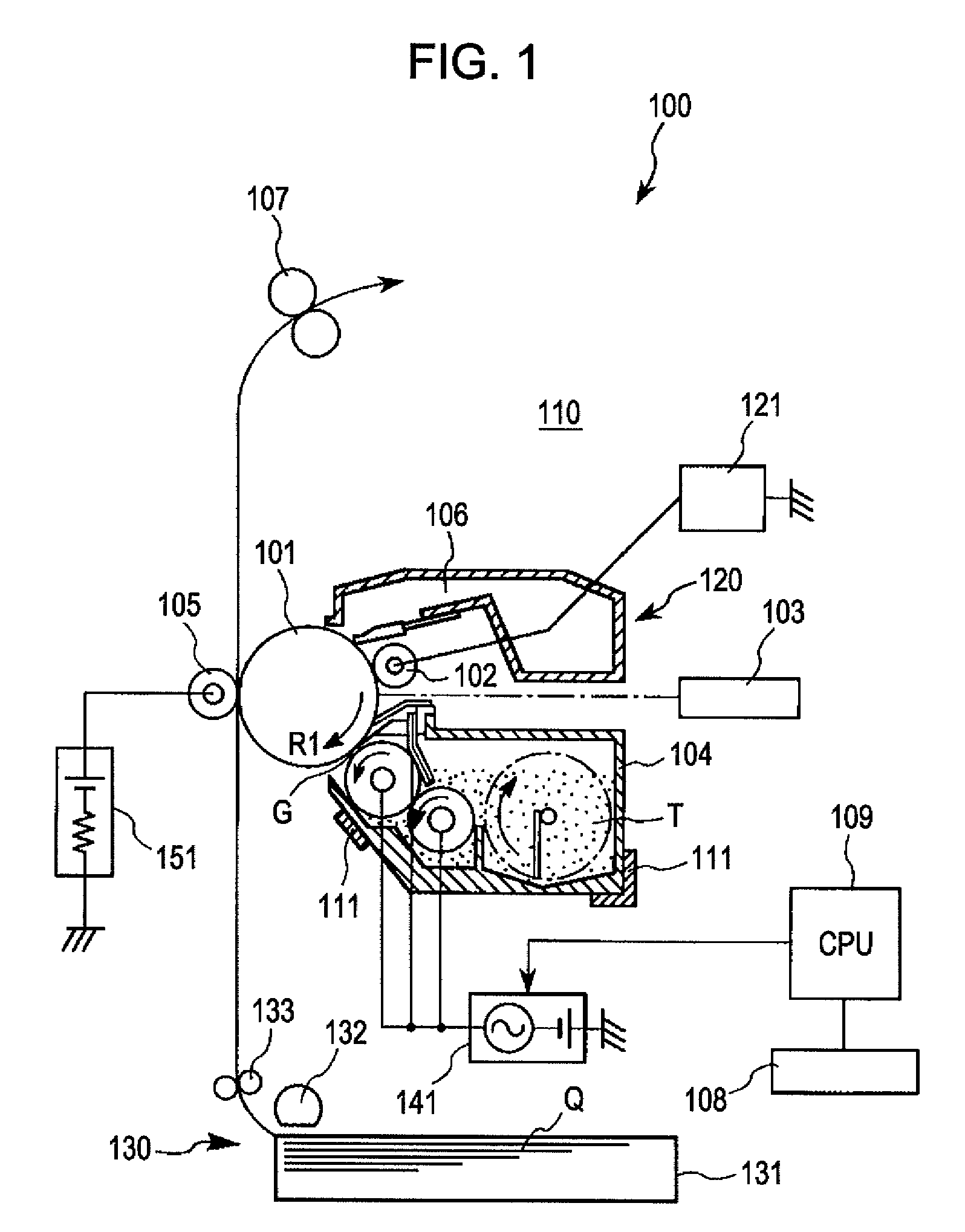
[0040] First, a general structure and an operation of an image forming apparatus according to an exemplary embodiment of the present invention are described. FIG. 1 shows an exemplary schematic structure of an image forming apparatus 100 according to this exemplary embodiment. In this exemplary embodiment, the image forming apparatus 100 is a laser-beam printer, which forms an image on a transfer material on the basis of an image information signal by electrophotography. The image information signal is sent to a main body 110 of the image forming apparatus 100 from an external apparatus (e.g., personal computer) connected to the main body 110 so as to be able to communicate with the main body 110. However, the present invention is not limited to the above structure. The present invention is widely applicable to other image forming apparatuses, such as a copier, a facsimile machine, or the like.

[0041] The image forming app...


PUM


Abstract

A developing device facing an image carrier and including a developer carrier, a developer flying control member, and a development-noise control member. The developing device develops an electrostatic image formed on the image carrier by causing the developer to fly from the developer carrier to the image carrier upon an application of an alternating-current bias to the developer carrier. Noise produced by the development-noise control member vibrated by an oscillating electric field of the alternating-current bias is smaller than a noise produced by the developer flying control member vibrated by the oscillating electric field.

Description

BACKGROUND OF THE INVENTION [0001] 1. Field of the Invention [0002] The present invention relates to a developing device for use in an image forming apparatus and to an image forming apparatus including the developing device. [0003] 2. Description of the Related Art [0004] An electrophotographic or electrostatic recording image forming apparatus, such as a copier, a printer, or other apparatuses electrostatically charges and then exposes an electrophotographic photosensitive member (photosensitive member) serving as an image carrier, thereby forming an electrostatic image (latent image) thereon. By developing the latent image by the use of toner being a developer, the apparatus forms toner images on the image carrier. The toner image is transferred to a transfer material (recording medium), such as a recording paper, a transparency, or other materials, directly or after being temporarily transferred to an intermediate transfer material. By fixing the toner image by the use of heat, ...

Claims


Application Information

Patent Timeline
Patent Type & Authority Applications(United States)
IPC IPC(8): G03G15/08
CPCG03G15/0813
Inventor MIYABE, SHIGEOSATO, MASAAKIANAN, OSAMU
Owner CANON KK
Learn More