In-building wireless enhancement system for high-rise with emergency backup mode of operation

a wireless enhancement and high-rise technology, applied in the field of distributed antenna systems, can solve the problems of system failure, useless system, and only effective simplex operation, and achieve the effect of enhancing in-building wireless communications

Inactive Publication Date: 2007-05-03
P G ELECTRONICS
View PDF4 Cites 54 Cited by
  • Summary
  • Abstract
  • Description
  • Claims
  • Application Information

AI Technical Summary

Problems solved by technology

Many facilities present problems for wireless radio frequency (RF) communication signals and require that an in-facility signal distribution system be employed to provide adequate wireless reception and coverage within the facility.
These problems exist for both RF signals that originate within the facility and RF signals that originate exterior to the facility.
These systems can provide good coverage for public service operation while the system is fully operational, but a loss of power can cause the system to cease operation and become useless.
Unfortunately, as has been shown in the past, simplex operation is only effective over short distances and only works over a few floors of a building before the signal is attenuated and contact is lost.

Method used


Image

  • In-building wireless enhancement system for high-rise with emergency backup mode of operation
  • In-building wireless enhancement system for high-rise with emergency backup mode of operation
  • In-building wireless enhancement system for high-rise with emergency backup mode of operation

Examples


Embodiment Construction

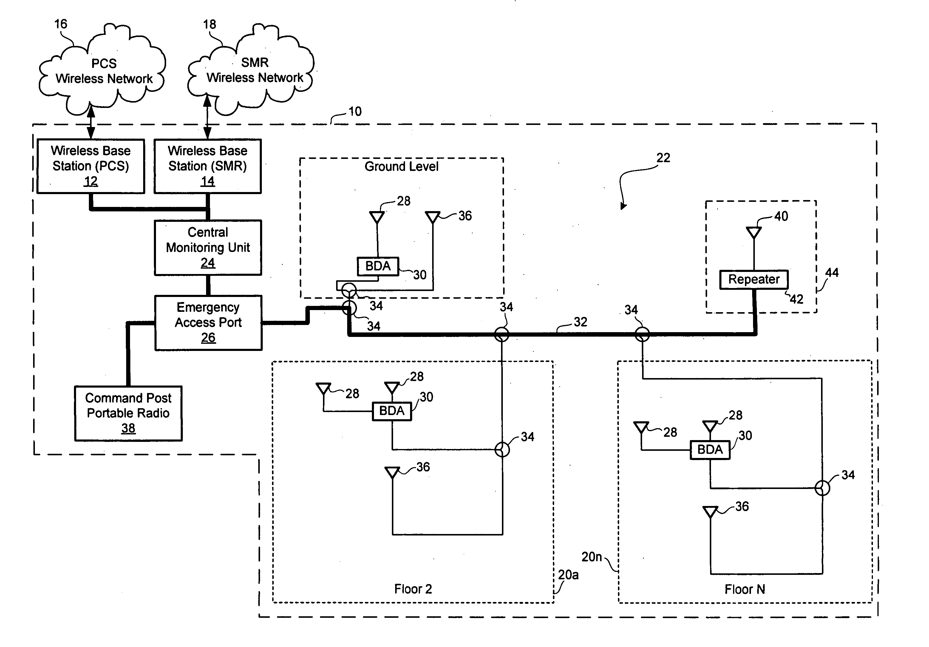
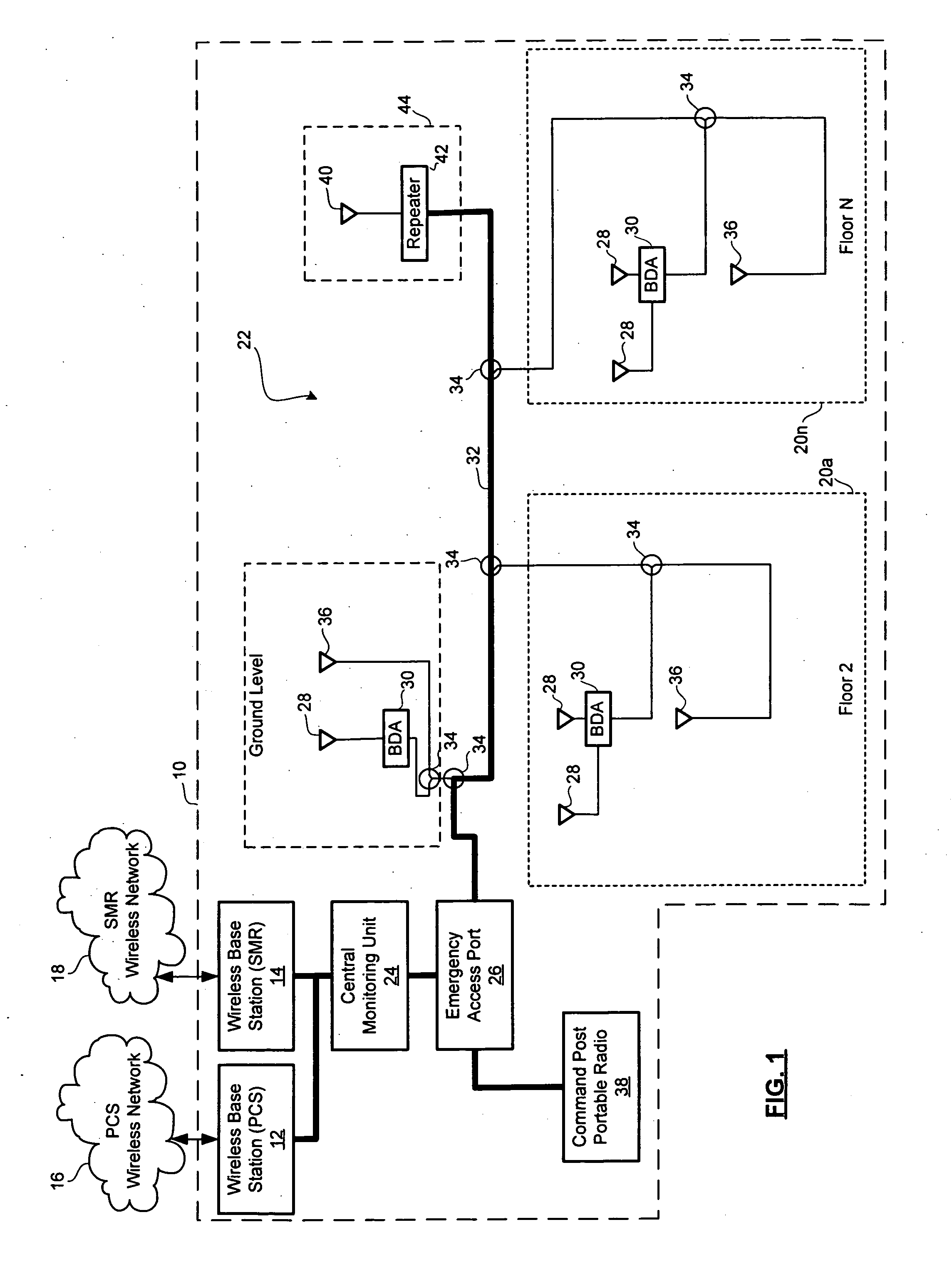
[0015] Referring to FIG. 1, a block diagram is shown of a system for providing communications to a facility 10 in accordance with one example of the present invention. The facility 10 has one or more wireless base stations, indicated by numerals 12 and 14, which are respectively coupled to wireless networks 16 and 18. The wireless networks 16 and 18 may be cellular networks, PCS networks, SMR band networks, paging networks, or other wireless communication networks for interfacing with mobile devices. The wireless networks 16 and 18 may operate using AMPS, DAMPS, NADC, CDMA, TDMA, GSM, iDEN or other modulation protocols. In one example, the wireless network 16 is a PCS network and the wireless base station 12 handles PCS signals while the wireless network 18 is a specialized mobile radio (SMR) network and the base station 14 handles SMR signals. Alternatively, in small facilities, the connection to the external networks 16 and 18 may be via repeaters to external base stations rather ...


PUM


Abstract

A distributed antenna system for providing distributed signal coverage within a facility of one or more wireless networks transmitting one or more RF signals. The distributed antenna system comprises a wireless base station configured to extend coverage of the one or more wireless networks; a backbone coupled to the base station; a plurality of coupler units connected to the backbone; a first plurality of antennas, each connected to one of the coupler units; a plurality of amplifiers coupled to the backbone; and a second plurality of antennas, each connected to one of the amplifiers. The plurality of amplifiers and the second plurality of antennas actively distribute the one or more RF signals during a powered condition and the first plurality of antennas passively distributes the one or more RF signals during a power failure.

Description

FIELD OF THE INVENTION [0001] The present invention relates to distributed antenna systems generally and, in particular, to an in-building wireless-enhancement system for a high-rise with an emergency backup mode of operation. BACKGROUND OF THE INVENTION [0002] Many facilities present problems for wireless radio frequency (RF) communication signals and require that an in-facility signal distribution system be employed to provide adequate wireless reception and coverage within the facility. These problems exist for both RF signals that originate within the facility and RF signals that originate exterior to the facility. Since RF waves in a building are attenuated not only by distance but also by losses caused by barriers such as concrete walls and floors, it is common to install enhancement systems in high-rise buildings. These enhancement systems boost the signals between portable electronic devices used in the building and external base stations responsible for sending and receivin...

Claims


Application Information

Patent Timeline
Patent Type & Authority Applications(United States)
IPC IPC(8): H04M1/00
CPCH01Q1/007H01Q13/203
Inventor GRAHAM, GERALDLIBER, PAUL
Owner P G ELECTRONICS
Why Eureka
Try Eureka